Temporary stringing construction device capable of crossing obstacles

A technology for construction devices and obstacles, applied in the direction of overhead lines/cable equipment, etc., can solve problems such as low efficiency of wire laying, deviation of wire laying from its installation position, and inconvenience of wire erection construction

Inactive Publication Date: 2021-04-23
陈景
View PDF0 Cites 0 Cited by
  • Summary
  • Abstract
  • Description
  • Claims
  • Application Information

AI Technical Summary

Problems solved by technology

[0003] When the wire falls off or needs to be strung up, usually a stringing construction device is needed to lift the wire, but in actual use, there are often obstacles under the part that needs to be stringed, which makes the stringing construction inconvenient, resulting in wires The laying deviates from its installation position, which makes the efficiency of wire laying low. Now a temporary wiring construction device that can cross obstacles is needed, which is convenient and quick for construction.

Method used


Image

  • Temporary stringing construction device capable of crossing obstacles
  • Temporary stringing construction device capable of crossing obstacles
  • Temporary stringing construction device capable of crossing obstacles

Examples


Embodiment 1

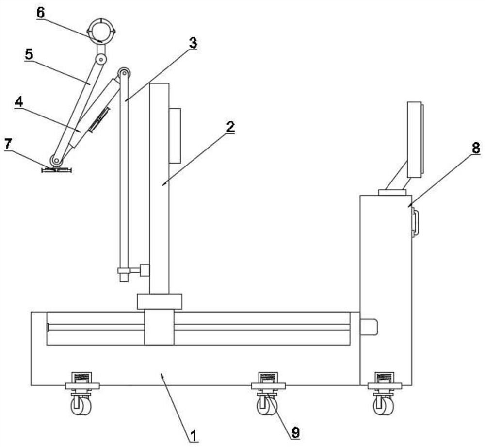
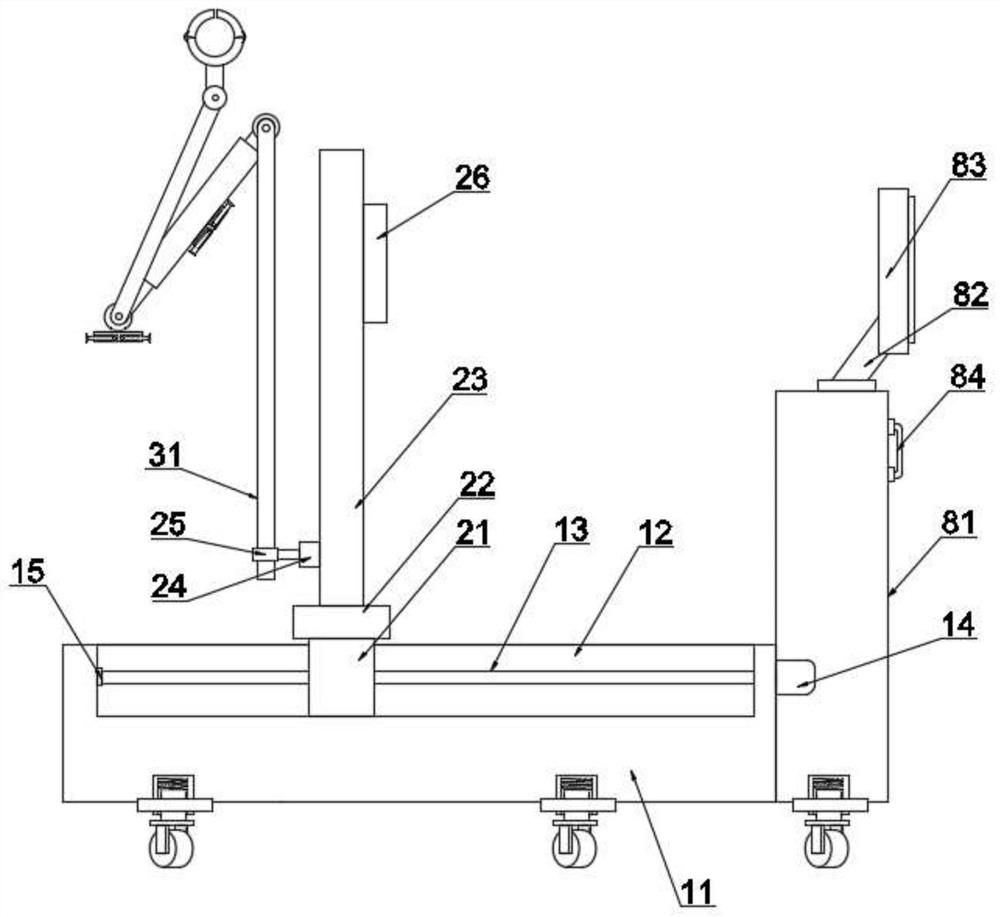
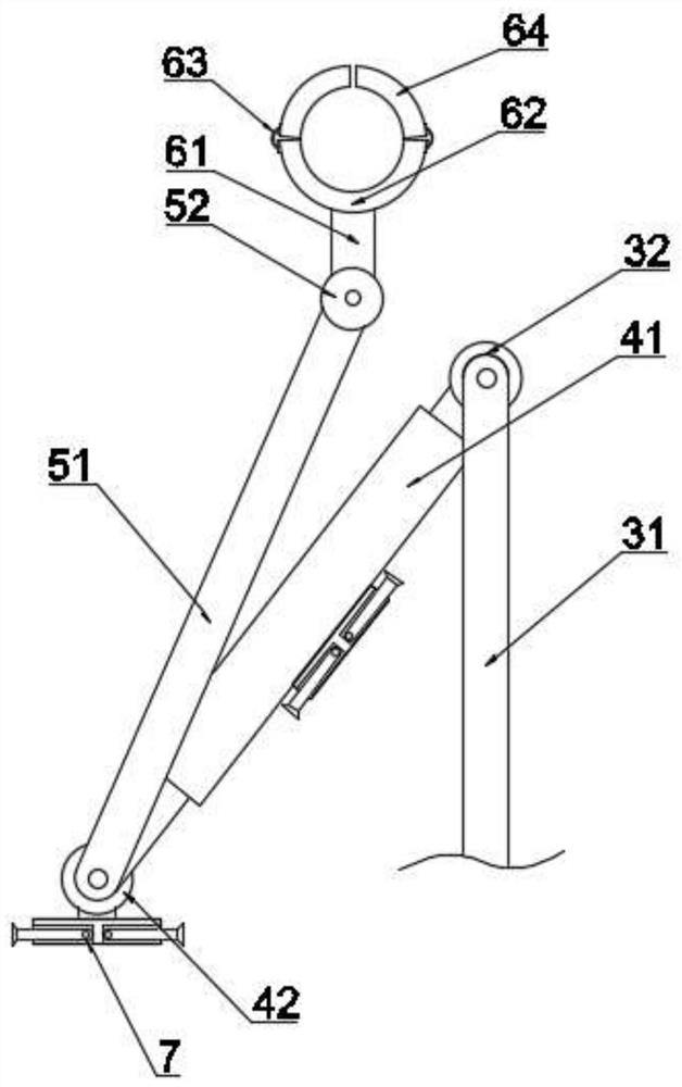
[0026] see Figure 1~6 , in an embodiment of the present invention, a temporary stringing construction device for crossing obstacles includes an installation platform 1, and the installation platform 1 includes a mounting seat 11, and a chute 12 is arranged in the upper end surface of the mounting seat 11, so that A telescopic cylinder mechanism 2 is slidably connected in the chute 12, and the telescopic cylinder mechanism 2 includes a slider 21, and the slider 21 is connected with a telescopic cylinder 23 through a connecting block 22, and a control box 26 is arranged on the telescopic cylinder 23. , the telescopic cylinder 23 is connected with a fixed collar 25 through a telescopic connection block 24, a first connecting mechanism 3 is installed in the fixed collar 25, and one end of the first connecting mechanism 3 away from the telescopic cylinder mechanism 2 is connected to the telescopic On the cross bar mechanism 4, the telescopic cross bar mechanism 4 is connected with...

Embodiment 2

[0040] see Figure 1~6 , on the basis of Embodiment 1, the bottom wheel mechanism 9 includes a rotating connection collar 91, and the rotating connection collar 91 is rotatably connected to the bottom surface of the mounting seat 11, and the rotating connecting collar 91 is installed through Sleeve 92.

[0041] The sleeve 92 has a cylindrical cylindrical structure, and a pin 94 is inserted through the sleeve 92, and the end of the pin 94 away from the sleeve 92 is connected with a bottom wheel 95, and the pin 94 and the sleeve 92 are provided with a Spring 93.


PUM


Abstract

The invention discloses a temporary stringing construction device capable of crossing obstacles, and relates to the technical field of power construction related equipment. The device comprises a mounting platform, the mounting platform comprises a mounting base, a sliding groove is formed in the upper end surface of the mounting base, a telescopic cylinder mechanism is slidably connected in the sliding groove, and the telescopic cylinder mechanism comprises a sliding block; the sliding block is connected with a telescopic cylinder through a connecting block, a control box is arranged on the telescopic cylinder, the telescopic cylinder is connected with a fixing lantern ring through a telescopic connecting block, a first connecting mechanism is installed in the fixing lantern ring, and the end, away from the telescopic cylinder mechanism, of the first connecting mechanism is connected to the telescopic transverse rod mechanism; and the telescopic transverse rod mechanism is connected with a clamping mechanism through a second connecting mechanism, a cable needing to be erected is supported through a clamping tray, and the cable is clamped through clamping jaws connected to the two sides of the clamping tray.

Description

technical field [0001] The invention relates to the technical field of equipment related to electric power construction, in particular to a temporary wiring construction device for crossing obstacles. Background technique [0002] Electricity is an energy source powered by electrical energy. Invented in the 1870s, the invention and application of electricity set off the second industrialization climax. It has become one of the three scientific and technological revolutions in the world since the 18th century in human history. Since then, technology has changed people's lives. The large-scale power system that appeared in the 20th century is one of the most important achievements in the history of human engineering science. It is a power production and consumption system composed of power generation, power transmission, power transformation, power distribution and power consumption. It converts the primary energy of nature into electricity through mechanical energy devices,...

Claims


Application Information

Patent Timeline
IPC IPC(8): H02G1/02H02G1/04
CPCH02G1/02H02G1/04
Inventor 陈景
Owner 陈景
Why Eureka
Try Eureka