Stator and permanent magnet motor

A permanent magnet motor and stator technology, applied in the direction of magnetic circuits, electric components, electrical components, etc., can solve the problems of low winding efficiency and inconvenience

Pending Publication Date: 2021-04-23
GREE ELECTRIC APPLIANCES INC +1
View PDF0 Cites 4 Cited by
  • Summary
  • Abstract
  • Description
  • Claims
  • Application Information

AI Technical Summary

Problems solved by technology

When the closed slot structure is adopted, since the stator teeth do not have slots, or the slot width is very small, it is very inconvenient for the stator to perform coil winding, and the winding efficiency is low

Method used


Image

  • Stator and permanent magnet motor
  • Stator and permanent magnet motor
  • Stator and permanent magnet motor

Examples


Embodiment Construction

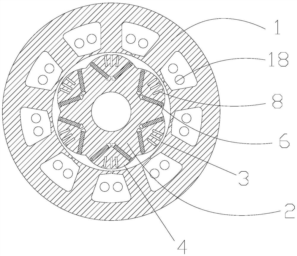
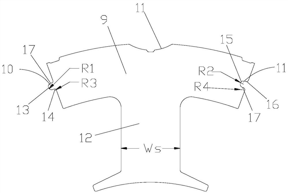
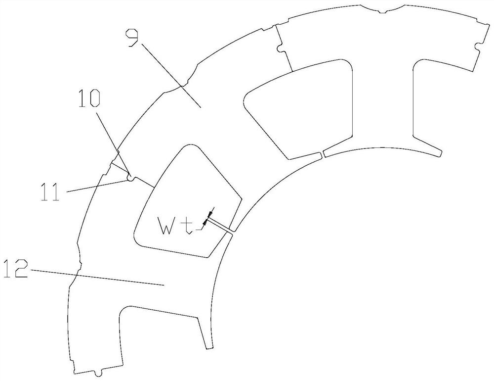
[0035] see in conjunction Figure 1 to Figure 10 As shown, according to the embodiment of the present application, the stator includes a plurality of iron core segments 9, and the plurality of iron core segments 9 are arranged in sequence along the circumferential direction. Each iron core segment 9 includes protrusions 10 and grooves 11, and the protrusions 10 is located on the first side surface of the iron core block 9 along the circumferential direction, the groove 11 is located on the second side surface of the iron core block 9 along the circumferential direction, the protrusion 10 matches the groove 11, each The protrusions 10 of the iron core segments 9 are embedded in the grooves 11 of the adjacent iron core segments 9 .

[0036] In this embodiment, the stator adopts a segmented structure. After winding each iron core segment 9, all the iron core segments 9 can be assembled into an integral stator. Since each iron core segment 9 They are all individually wound, so th...


PUM


Abstract

The invention provides a stator and a permanent magnet motor. The stator comprises a plurality of iron core blocks (9) which are sequentially arranged in the circumferential direction, each iron core block (9) comprises a protrusion (10) and a groove (11), the protrusions (10) are located on the first side surfaces of the iron core blocks (9) in the circumferential direction, the grooves (11) are located on the second side surfaces of the iron core blocks (9) in the circumferential direction, and the protrusions (10) are matched with the grooves. And the bulge (10) of each iron core block (9) is embedded into the groove (11) of the adjacent iron core block (9). According to the stator provided by the invention, the coil winding difficulty of the stator can be reduced, and the stator coil winding efficiency is improved.

Description

technical field [0001] The present application relates to the technical field of motors, in particular to a stator and a permanent magnet motor. Background technique [0002] Permanent magnet motors are widely used in various industries due to their high energy efficiency and high speed regulation performance, such as fans, water pumps, and air compressors in the industrial field. Permanent magnet motors are also gradually entering the household field. At present, the traditional technical route is mainly two types of rare earth permanent magnet motor and reluctance motor. Because the stator winding of the reluctance motor needs to adopt a distributed coil structure, the copper wire at the end is seriously wasted. In low-power models, the permanent magnet of the reluctance motor The cost advantage is not enough to make up for the disadvantage of the large amount of enameled wire, so the permanent magnet motor for the small power segment (usually defined as 0.35-2.2kW) is sti...

Claims


Application Information

Patent Timeline
Patent Type & Authority Applications(China)
IPC IPC(8): H02K1/14H02K1/27H02K3/28H02K1/16
CPCH02K1/148H02K1/165H02K1/276H02K3/28H02K2201/03H02K2213/03
Inventor 胡余生童童陈彬张健蒋云龙李世鹏
Owner GREE ELECTRIC APPLIANCES INC
Why Eureka
Try Eureka