
Laser apparatus

A laser device and laser beam technology, applied in laser welding equipment, installation, optics, etc., can solve the problems of poor processing quality of the processed object, not including the laser beam, and unable to quickly respond to the bending of the optical path of the laser beam, etc.

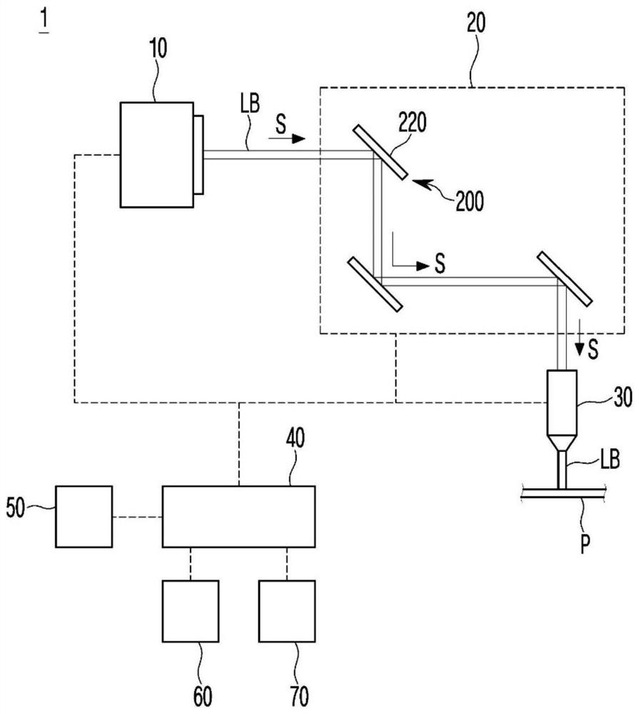
Pending Publication Date: 2021-04-27
NPS CO LTD
View PDF0 Cites 0 Cited by
  • Summary
  • Abstract
  • Description
  • Claims
  • Application Information

AI Technical Summary

Problems solved by technology

Therefore, the laser beam emitted from the laser nozzle irradiates the object to be processed in a state deviated from the predetermined processing position, thereby adversely affecting the processing quality of the object to be processed.
[0005] Therefore, the existing laser device does not include a structure capable of diagnosing and correcting the bending of the optical path of the laser beam, and thus cannot quickly cope with the bending of the optical path of the laser beam.

Method used


Image

  • Laser apparatus
  • Laser apparatus
  • Laser apparatus

Examples


Embodiment Construction

[0085] Hereinafter, some embodiments of the present invention will be described in detail through illustrative drawings. In attaching reference numerals to constituent elements in each drawing, even if they are shown in different drawings, the same constituent elements are given the same reference numerals as much as possible. Also, in describing the embodiments of the present invention, when it is judged that a specific description of a related known structure or function hinders the understanding of the embodiments of the present invention, the detailed description thereof will be omitted.

[0086] In describing the structural elements of the embodiments of the present invention, the terms of first, second, A, B, (a), (b), etc. may be used. The above terms are only used to distinguish two kinds of structural elements, and the nature or order or sequence of the corresponding structural elements are not limited to the terms. And, as long as they are not clearly defined, all t...


PUM


Abstract

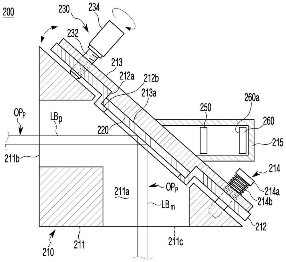
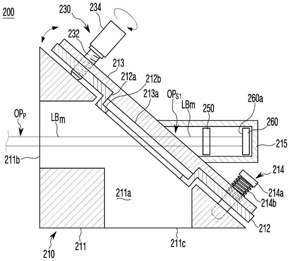
The invention relates to a laser device which comprises a laser oscillator, a lens frame assembly, a corrector, a diagnosis module, a calculation module and a controller. The diagnosis module re-diagnoses whether or not the optical path bend occurs by re-calculating an optical path difference between the processing optical path and the reference processing optical path, the optical path difference being changed by the drive motor according to the target drive speed and the target drive time. When the optical path difference after the recalculation is greater than the reference optical path difference, the calculation module recalculates the target drive speed and the target drive time based on the optical path difference after the recalculation. The controller redrives the drive motor according to the recalculated target drive speed and the recalculated target drive time.

Description

technical field [0001] The present invention relates to laser devices. Background technique [0002] Recently, in the field of processing devices such as cutting devices, marking devices, etc., the use of laser beams having excellent physical characteristics is increasing day by day. [0003] Generally, a laser device includes: a laser oscillator that generates a laser beam to oscillate; an optical system that transmits the laser beam oscillated in the laser oscillator according to a preset transmission method; and a laser nozzle that condenses the laser beam transmitted through the optical system. Light is irradiated to the object to be processed. [0004] On the other hand, if the correction state of the optical components installed in the optical system changes due to external force and vibration, wear and aging of the structural elements of the laser device, and other reasons, so that the optical path of the laser beam is bent, the laser beam It will be sent to the las...

Claims


Application Information

Patent Timeline
Patent Type & Authority Applications(China)
IPC IPC(8): B23K26/042B23K26/70G02B7/182G02B7/198
CPCB23K26/042B23K26/702G02B7/182G02B7/198B23K26/043B23K26/1462G02B7/1827G06N20/00B23K26/38G01M11/0221G02B26/0816G05B19/401G05B2219/4719
Inventor 裵城晧
Owner NPS CO LTD
Learn More