
Efficient steel pipe sheet spot welding jig

A steel pipe and sheet point technology, applied in the field of high-efficiency steel pipe sheet spot welding fixtures, can solve problems such as cumbersome operation, reduced steel pipe sheet tailor welding efficiency, and complex structure

Pending Publication Date: 2021-04-27
江苏银旭隧道机械有限公司
View PDF1 Cites 0 Cited by
  • Summary
  • Abstract
  • Description
  • Claims
  • Application Information

AI Technical Summary

Problems solved by technology

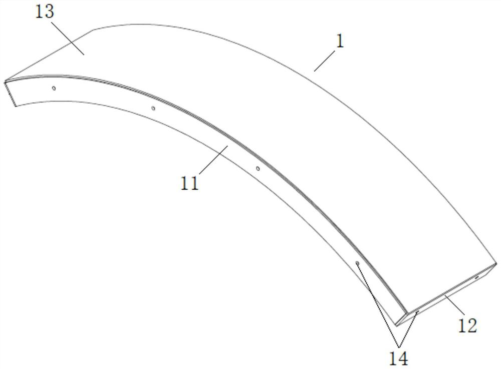
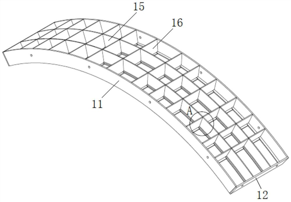
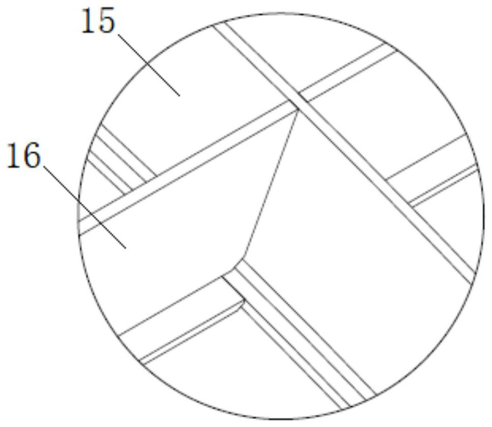
[0002] When excavating large-diameter tunnels, due to geological conditions and tunnel reliability requirements, steel pipe sheets are used for full-face support; Figure 1-3 As shown, the steel pipe sheet 1 includes a frame body; the frame body is composed of two side plates 11 and two end plates 12; the upper end of the frame body 1 is provided with a cover plate 13; the frame body 1 is provided with several transverse partitions 16 and longitudinal partitions 15; the cross-sections of the transverse partitions 16 and the longitudinal partitions 15 are all in an inverted T-shape; at present, in the production process of steel pipe sheets, most of them adopt the method of manual tailor welding, which is not only time-consuming and laborious, The work efficiency is low, and there is the problem of insufficient positioning accuracy of the horizontal partition and the longitudinal partition; although there are also tailor-welded fixtures on the market, such as a large-diameter steel pipe piece tailor-weld method disclosed in the prior art 202010953513.X, although it can Reduce the difficulty of welding and improve the quality of the weld seam, but the structure is complex and the operation is cumbersome, which not only increases the manufacturing cost of tailor welding fixtures, but also reduces the efficiency of tailor welding of steel pipe pieces

Method used


Image

  • Efficient steel pipe sheet spot welding jig
  • Efficient steel pipe sheet spot welding jig
  • Efficient steel pipe sheet spot welding jig

Examples


Embodiment Construction

[0024] The present invention will be further described in detail below in conjunction with the accompanying drawings and specific embodiments.

[0025] attached Figure 4-8 It is a high-efficiency steel pipe sheet spot welding fixture according to the present invention, which includes a base 21, two side connecting plates 22 and two end connecting plates 23; the top of the base 21 is provided with a plurality of arched support plates 24; A plurality of support plates 24 are evenly spaced along the width direction of the base 21, and the two support plates 24 on the outside are respectively located on both sides of the top of the base 21; the same side of the top of the plurality of support plates 24 are provided There are positioning strips 25; each of the positioning strips 25 is provided with a plurality of positioning slots 251 evenly spaced along the length direction of the base 21; the two side connecting plates 22 are arched, and are respectively arranged on the base 21 ...


PUM


Abstract

The invention relates to an efficient steel pipe sheet spot welding jig. The efficient steel pipe sheet spot welding jig comprises a base, two side connecting plates and two end connecting plates. A plurality of arched supporting plates are arranged at the top of the base. The plurality of supporting plates are evenly arranged in the width direction of the base at intervals, and the two supporting plates located on the outer side are located on the edges of the two sides of the top of the base correspondingly. The same sides of the tops of the supporting plates are each provided with positioning strips. Each positioning strip is provided with a plurality of positioning grooves which are evenly formed in the length direction of the base at intervals. The two side connecting plates are both in an arch shape and are arranged on the two sides of the top of the base correspondingly. The two end connecting plates are arranged at the two ends of the top of the base correspondingly, placed in the radial direction of the axis of the supporting plate and connected with the two ends of the supporting plates correspondingly. The tailor-welding efficiency of steel pipe sheets is greatly improved, the shape and position precision of the steel pipe sheets is guaranteed, and the efficient steel pipe sheet spot welding jig has the advantages of being simple in structure, convenient to operate, low in manufacturing cost and the like.

Description

technical field [0001] The invention relates to the technical field of tunnels, in particular to a high-efficiency spot welding fixture for steel pipe sheets. Background technique [0002] When excavating large-diameter tunnels, due to geological conditions and tunnel reliability requirements, steel pipe sheets are used for full-face support; Figure 1-3 As shown, the steel pipe sheet 1 includes a frame body; the frame body is composed of two side plates 11 and two end plates 12; the upper end of the frame body 1 is provided with a cover plate 13; the frame body 1 is provided with several transverse partitions 16 and longitudinal partitions 15; the cross-sections of the transverse partitions 16 and the longitudinal partitions 15 are all in an inverted T-shape; at present, in the production process of steel pipe sheets, most of them adopt the method of manual tailor welding, which is not only time-consuming and laborious, The work efficiency is low, and there is the problem o...

Claims


Application Information

Patent Timeline
IPC IPC(8): B23K37/04
CPCB23K37/0443
Inventor 张银生薛晓张宇峰席琪凯
Owner 江苏银旭隧道机械有限公司
Learn More