Bionic non-pneumatic tire

A non-pneumatic tire and tread technology, which is applied to non-pneumatic tires, tire parts, transportation and packaging, etc., can solve the problems of poor shock absorption performance and loud noise

Pending Publication Date: 2021-04-27
特拓(青岛)轮胎技术有限公司
View PDF1 Cites 0 Cited by
  • Summary
  • Abstract
  • Description
  • Claims
  • Application Information

AI Technical Summary

Problems solved by technology

[0004] Aiming at the above-mentioned problems of poor damping performance and high noise in existing air-free tires, the present invention provides a bionic air-free tire, which can effectively buffer large vibrations through a Z-shaped buffer structure and a diamond-shaped honeycomb structure. , and can effectively buffer small vibrations, break the frequency of wind noise, reduce the wind noise of non-inflatable tires, and avoid the problem of permanent deformation of the single structure itself due to insufficient strength

Method used


Image

  • Bionic non-pneumatic tire
  • Bionic non-pneumatic tire
  • Bionic non-pneumatic tire

Examples


Embodiment 1

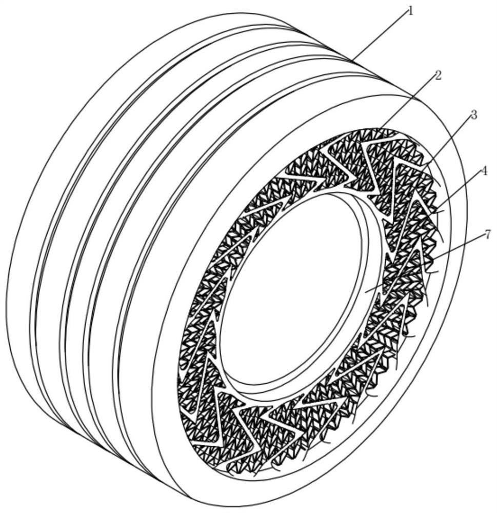
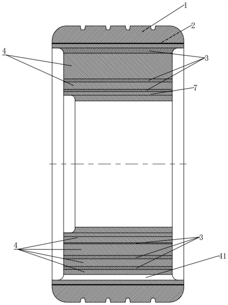
[0028] Such as figure 1 As shown, a bionic air-free tire includes a tread 1, a connecting layer 2, a bionic cushioning structure and an installation body 7 from outside to inside in sequence, and the above-mentioned parts are closely connected to form a whole. The tread 1 is directly in contact with the ground, and its surface is provided with tire patterns. The tread 1 is preferably a nano-rubber layer. The connecting layer 2 is an adhesive material, which tightly connects the tread 1 with the bionic buffer structure. The installation body 7 is an installation part of the tire, and the bionic tire is fixedly connected with the vehicle through the installation body 7 .

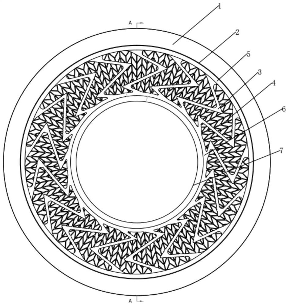
[0029] Such as figure 2 As shown, the bionic buffer structure is composed of a Z-shaped buffer plate 3 imitating the hind limbs of a cat, a diamond-shaped honeycomb elastic body 4 , a first outer ring 5 and a first inner ring 6 . The first outer ring 5 is set close to the connection layer 2, the first inn...

Embodiment 2

[0036] Such as Figure 5 As shown, a bionic air-free tire includes a tread, a connecting layer, a bionic buffer structure, an adaptive buffer structure and an installation body in sequence from outside to inside. Compared with Example 1, the bionic air-free tire has an adaptive buffer structure added.

[0037] The tread, connecting layer and adaptive cushioning structure are similar to those in Embodiment 1.

[0038] Such as Figure 6 As shown, the adaptive buffer structure is composed of an I-shaped buffer plate 8, a second outer ring 9 and a second inner ring 10, the second outer ring 9 is close to the first inner ring 6, and the second inner ring 10 is close to the mounting body 7 , an annular area is formed between the second outer ring 9 and the second inner ring 10, the I-shaped buffer plate 8 is radially distributed in the annular area along the second inner ring 10, and the I-shaped buffer plate 8 is relatively to the second inner ring The ring 10 is arranged obliqu...


PUM

PropertyMeasurementUnit
Thicknessaaaaaaaaaa
Thicknessaaaaaaaaaa

Abstract

The invention belongs to the technical field of tires. Aiming at the problems of poor shock absorption performance and high noise of the existing non-pneumatic tire, the invention provides a bionic non-pneumatic tire which sequentially comprises a tread, a connecting layer, a bionic buffer structure and a mounting body from outside to inside, the bionic buffer structure comprises a Z-shaped buffer plate imitating the hind limb of a feline, a honeycomb-shaped elastic body, a first outer ring and a first inner ring; the area among the Z-shaped buffer plate, the first outer ring and the first inner ring is filled with the honeycomb-shaped elastic body, and holes of the honeycomb-shaped elastic body is gradually enlarged from the first inner ring to the first outer ring. By means of the Z-shaped buffer structure and the rhombic honeycomb structure, the tire can effectively buffer large vibration and small vibration, the wind noise frequency is broken through, the wind noise of the inflation-free tire is reduced, and the problem that permanent deformation occurs due to insufficient strength of a single structure is solved.

Description

technical field [0001] The invention belongs to the technical field of tires, in particular to a bionic air-free tire. Background technique [0002] For a long time, the tires commonly used in vehicles are pneumatic tires. The superior cushioning performance and low rolling resistance of pneumatic tires have not been surpassed by other tires so far. However, pneumatic tires require regular tire pressure maintenance, are prone to puncture and air leakage, and have serious consequences for tire blowouts. Non-pneumatic tires, that is, tires that do not need to be inflated, do not rely on air, and only use the tire's own material and structure to achieve support and cushioning performance, such as solid tires, spring tires, buffer tires, etc. However, the existing non-inflatable tires generally have the defects of poor comfort performance, weak shock absorption capacity, high noise, and high fuel consumption. Therefore, it is difficult to popularize and apply them in the civili...

Claims


Application Information

Patent Timeline
IPC IPC(8): B60C7/00B60C7/10
CPCB60C7/00B60C7/10
Inventor 李红卫吴长辉顾培霜薛伯勇
Owner 特拓(青岛)轮胎技术有限公司
Why Eureka
Try Eureka