Feeding method and multi-channel feeding machine

A feeder, multi-channel technology, applied in the direction of conveyor objects, transportation and packaging, etc., can solve the problems of easy sticking together, difficult to divide materials, and difficult to use automatic equipment to supply materials.

Pending Publication Date: 2021-04-27
QKM TECH (DONG GUAN) CO LTD
View PDF16 Cites 0 Cited by
  • Summary
  • Abstract
  • Description
  • Claims
  • Application Information

AI Technical Summary

Problems solved by technology

However, for some soft materials (such as packaging bags), it is difficult to separate materials because they are easy to stick together, making it difficult to use automated equipment for feeding

Method used


Image

  • Feeding method and multi-channel feeding machine
  • Feeding method and multi-channel feeding machine
  • Feeding method and multi-channel feeding machine

Examples


Embodiment 1

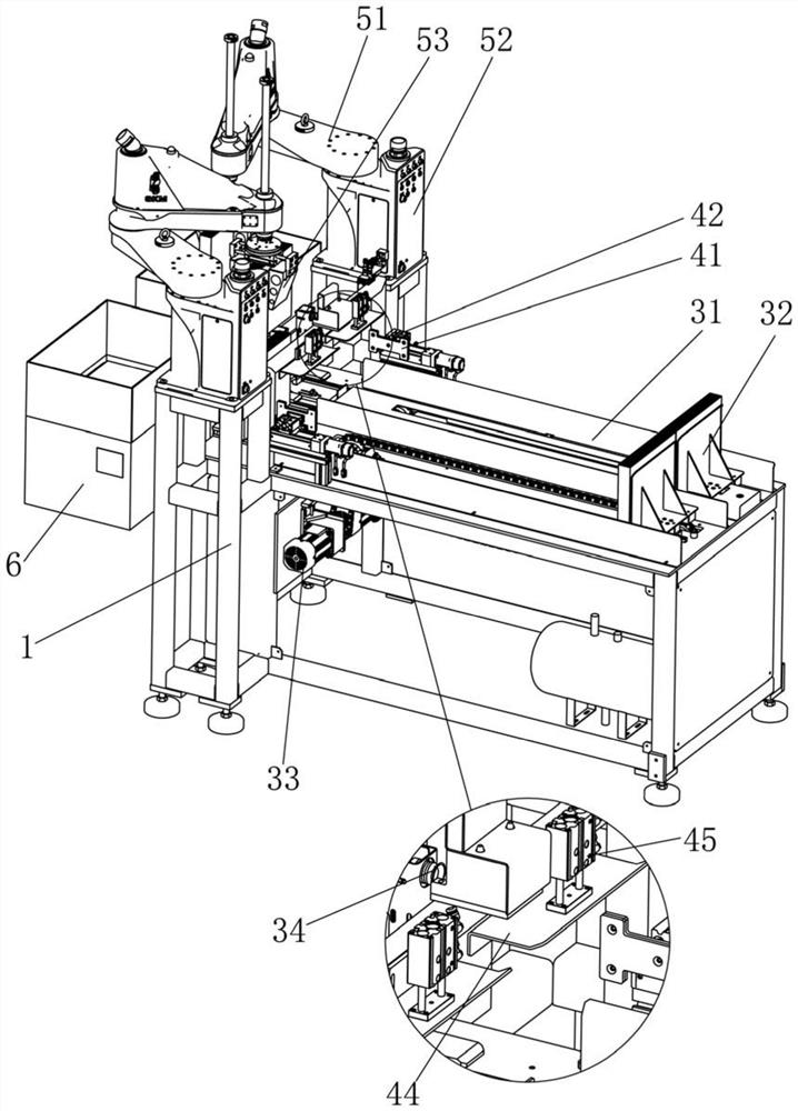
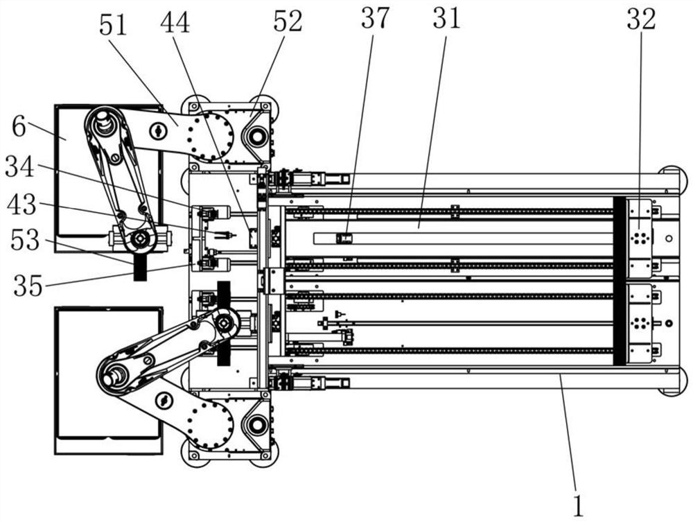
[0030] This embodiment provides a material feeding method, which includes the following steps in sequence: S1: setting a predetermined vacuum value; S2: pushing a plurality of materials that are stacked one after another away from the suction cup 34, so that the materials closest to the suction cup 34 collide with the suction cup 34 To be adsorbed by the suction cup 34, and detect the vacuum value in the suction cup 34 during the pushing process; S3: When it is detected that the vacuum value in the suction cup 34 is equal to the predetermined vacuum value set in S1, stop pushing the stacked multiple materials; S4: fix the material next to the suction cup 34; S5: move the suction cup 34 to separate the material closest to the suction cup 34 from the material next to the suction cup 34.

[0031] The purpose of detecting the vacuum value in the suction cup 34 in step S2 is to detect whether the suction cup 34 has adsorbed the material stably. Since the suction cup 34 has differen...

Embodiment 2

[0038] The difference between this embodiment and the first embodiment is that in step S1, the materials of the plurality of materials are detected, and pre-stored values ​​are selected in the database according to the detection results, and the predetermined vacuum value is set with the selected pre-stored values. This can reduce manual operations and further improve the automation of the entire feeding process. Specifically, a CCD camera or other image acquisition equipment may be used to collect the image of the material, and then an image analysis technology may be used to analyze the material of the material.

Embodiment 3

[0040] The difference between this embodiment and the first embodiment is that in step S1, the server remotely sets the preset vacuum value through the communication module 8 . This allows the user to remotely set the vacuum preset value using the server, thereby improving the convenience and efficiency of the feeding process.


PUM


Abstract

The invention relates to the technical field of feeding equipment, in particular to a feeding method and a multi-channel feeding machine. The feeding method sequentially comprise the following steps: S1, setting a vacuum preset value; S2, pushing the stacked materials away from a suction cup in sequence, enabling the material closest to the suction cup to abut against the suction cup to be adsorbed by the suction cup, and detecting a vacuum value in the suction cup in the pushing process; S3, when it is detected that the vacuum value in the suction cup is equal to the vacuum preset value set in the step S1, stopping pushing the stacked materials; S4, fixing the material close to the suction cup in sequence; and S5, moving the suction cup so that the material closest to the suction cup can be separated from the material secondly close to the suction cup. According to the feeding method and the multi-channel feeding machine, the suction cup is used for adsorbing materials and detecting the vacuum value in the suction cup to determine whether the materials are successfully adsorbed or not, and the suction cup is moved to separate the materials, so that the separation of the soft materials is realized, and the effect of feeding the soft materials by using automatic equipment is achieved.

Description

technical field [0001] The invention relates to the technical field of feeding equipment, in particular to a feeding method and a multi-channel feeding machine. Background technique [0002] In order to reduce labor intensity and improve production efficiency, many industries will use automated equipment for feeding. However, for some soft materials (such as packaging bags), it is difficult to separate materials because they are easy to stick together, making it difficult to use automated equipment for feeding. Contents of the invention [0003] Aiming at the problems of the prior art, the invention provides a feeding method capable of distributing soft materials. [0004] The present invention adopts the following technical scheme: a feeding method, including the following steps in sequence: S1: setting a predetermined vacuum value; S2: pushing a plurality of materials that are stacked and successively away from the suction cup, so that the material closest to the suctio...

Claims


Application Information

Patent Timeline
Patent Type & Authority Applications(China)
IPC IPC(8): B65G47/91
CPCB65G47/917
Inventor 任伟平石金博邬荣飞
Owner QKM TECH (DONG GUAN) CO LTD
Why Eureka
Try Eureka