
X-shaped connection double-limb buckling-restrained brace

A technology of anti-buckling braces and connectors, which is applied in the direction of earthquake resistance, building types, buildings, etc., can solve the problems of buckling-resistant braces’ overall buckling instability and withdrawal, so as to improve the ability of secondary energy consumption and shock absorption, good shape recovery ability, Improve the effect of energy dissipation and shock absorption capacity

Pending Publication Date: 2021-04-27
CHONGQING UNIV
View PDF0 Cites 2 Cited by
  • Summary
  • Abstract
  • Description
  • Claims
  • Application Information

AI Technical Summary

Problems solved by technology

The traditional single anti-buckling brace does not always play its role well in large-span spatial structures. During the earthquake, the buckling-resistant bracing may cause overall buckling instability and withdraw from work.

Method used


Image

  • X-shaped connection double-limb buckling-restrained brace
  • X-shaped connection double-limb buckling-restrained brace
  • X-shaped connection double-limb buckling-restrained brace

Examples


Embodiment 1

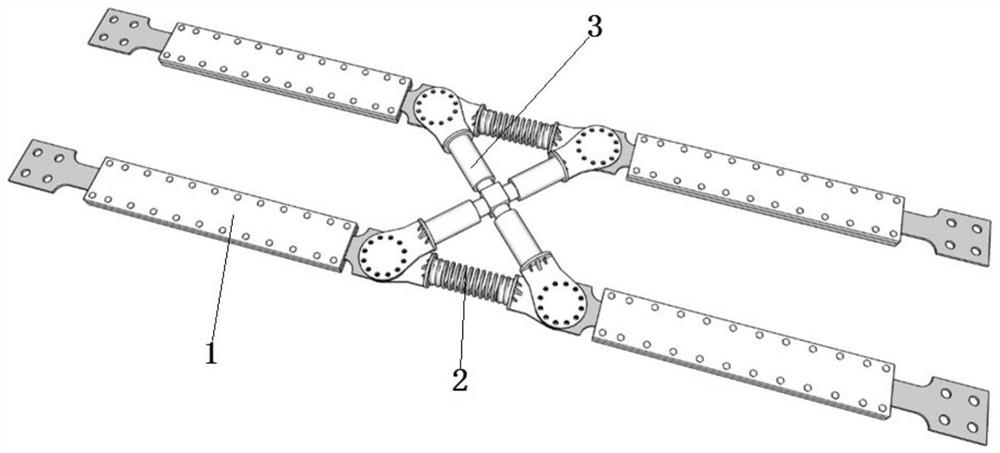
[0041] This embodiment discloses an X-shaped joint anti-buck support for both limbs, which includes an anti-buck support member 1 , a reset connector 2 and an X-shaped connector 3 .

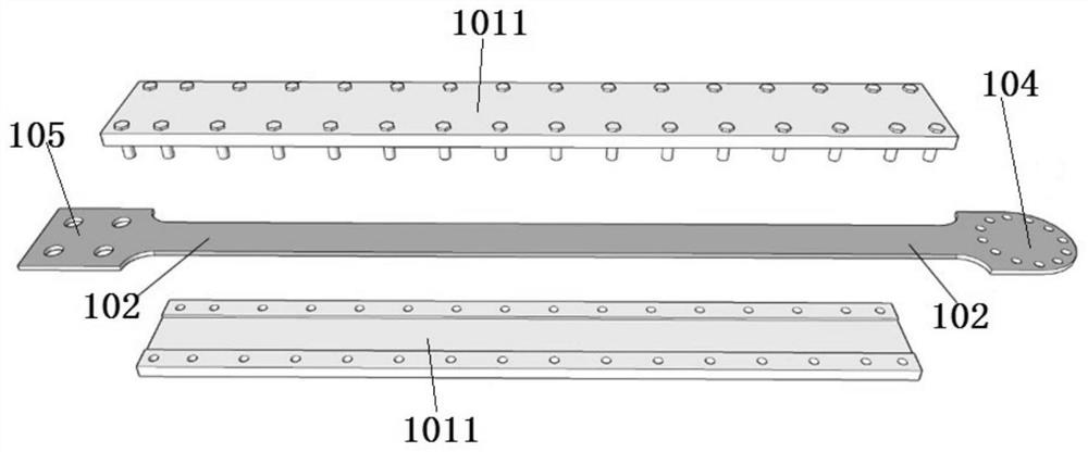
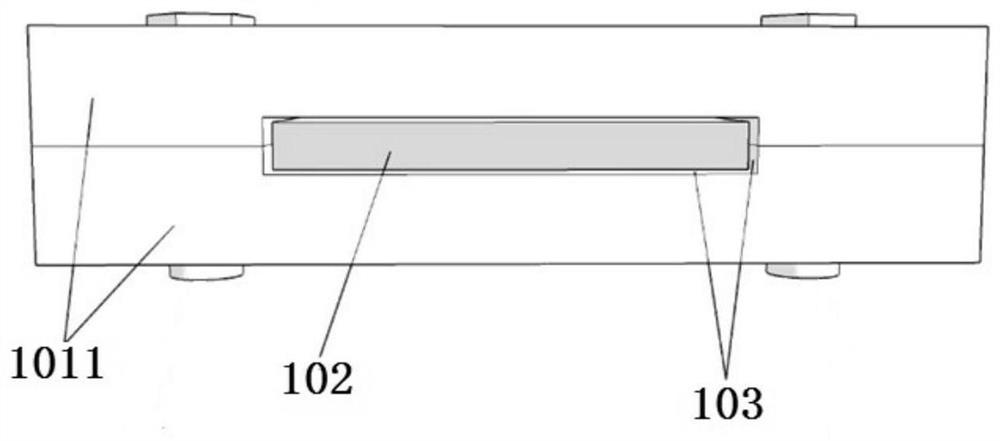
[0042] The anti-buckling support member 1 includes a supporting shell 101 and an energy-dissipating core material 102 , and the material yield value of the energy-dissipating core material 102 is smaller than that of the supporting shell 101 .

[0043] see figure 2 , the supporting shell 101 is spliced ​​by two constraining plates 1011, and one side of the constraining plate 1011 is provided with a rectangular through-slot running through both ends thereof.

[0044] The slots of the two constraining plates 1011 face each other and are connected by several bolts. The two rectangular through slots are spliced ​​to form a cavity S. The energy-dissipating core material 102 in the shape of a rectangular plate is installed in the two cavities S. The energy-dissipating core material The two ends of 10...

Embodiment 2

[0058] The structure of this embodiment is similar to that of Embodiment 1, the difference is that the structure of the anti-buckling support member 1 is different, specifically, see Figure 7 Or 8, the support shell 101 of this embodiment is a round tube, and the support shell 101 is filled with fillers 106 to form a cavity S with an in-line cross section, and the energy-dissipating core material 102 with a in-line cross-section is installed in the cavity S, Two ends of the energy dissipation core material 102 protrude from the supporting shell 101 . The two protruding ends of the energy dissipation core material 102 are integrally formed with a joint I 104 and a joint II 105 .

[0059] see Figure 8 , a filling material 103 is arranged between the energy dissipation core material 102 and the filling 106 .

Embodiment 3

[0061] The structure of this embodiment is similar to that of Embodiment 2, the difference is that the cross-sectional shape of the cavity S is different, specifically, see Figure 9 , the supporting shell 101 of this embodiment is filled with fillers 106 to form a cavity S with a cross-shaped cross-section, and the energy-dissipating core material 102 with a cross-shaped cross-section is installed in the cavity S. Extend the support case 101 . The two protruding ends of the energy dissipation core material 102 are integrally formed with a joint I 104 and a joint II 105 .

[0062] see Figure 9 , a filling material 103 is arranged between the energy dissipation core material 102 and the filling 106 .


PUM


Abstract

The invention discloses an X-shaped connection double-limb buckling-restrained brace, and relates to the technical field of earthquake resistance and disaster prevention of building structures. The X-shaped connection double-limb buckling-restrained brace comprises a buckling-restrained brace member part, a reset connecting piece and an X-shaped connecting piece. According to the X-shaped connection double-limb buckling-restrained brace, four independent buckling-restrained brace members ingeniously form the X-shaped connection double-limb buckling-restrained brace through reset connection and X-shaped connection, the energy dissipation and shock absorption capacity of a single buckling-restrained brace is reserved, and meanwhile, the overall energy dissipation and shock absorption capacity of the buckling-restrained brace is improved through the ingenious design of the reset connection part and the X-shaped connection part; and the buckling-restrained brace has certain self-resetting capacity after the structure is subjected to load action such as earthquake through springs, and the secondary energy dissipation and shock absorption capacity of the buckling-restrained brace is improved.

Description

technical field [0001] The invention relates to the technical field of earthquake resistance and disaster prevention of building structures, in particular to a novel buckling-resistant support form. Background technique [0002] Long-span spatial structures and high-rise structures are more and more widely used in practical engineering. Such large-scale structures may be damaged by local structures first under the action of accidental loads such as earthquakes, which may cause damage to the overall structure. In order to prevent such damage, an effective measure is to set anti-buckling braces in it. The traditional single anti-buckling brace does not always play its role well in large-span spatial structures, and the buckling-resistant brace may fail to work due to overall buckling instability during earthquakes. For this reason, it is of great significance to develop a new buckling-resistant brace that can meet the requirements of large-span structures working under strong...

Claims


Application Information

Patent Timeline
Patent Type & Authority Applications(China)
IPC IPC(8): E04B1/98E04H9/02
CPCE04B1/98E04H9/021
Inventor 李鹏程李志强王昊简斌郭莹
Owner CHONGQING UNIV
Learn More