Design table for development of smart office OA system

A smart, design board technology, applied to computer workstation desks or desks, applications, home appliances, etc., can solve the problems that affect design efficiency, the angle of the design table top cannot be adjusted according to the use requirements, and the design paper is not easy to fix, etc., to achieve The effect of improving design efficiency

Active Publication Date: 2021-04-30
中通服供应链股份有限公司
View PDF8 Cites 2 Cited by
  • Summary
  • Abstract
  • Description
  • Claims
  • Application Information

AI Technical Summary

Problems solved by technology

[0004] The invention proposes a design table for the development of an intelligent office OA system, which solves the problem that the angle of the table top of the existing design table cannot be adjusted according to the use requirements and the design paper is not easy to fix, which affects the design efficiency.

Method used


Image

  • Design table for development of smart office OA system
  • Design table for development of smart office OA system
  • Design table for development of smart office OA system

Examples


Embodiment 1

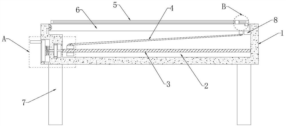
[0028] refer to figure 1 , Figure 5 with Image 6 , a design platform for smart office OA system development, including a platform 1, the four corners of the bottom end of the platform 1 are fixedly connected with support columns 7, and the top of the platform 1 is provided with a mounting groove 2, and one side of the mounting groove 2 The inner wall is rotatably equipped with a design board 6, and the front of the design board 6 is provided with a paper positioning mechanism, and the side of the platen 1 near the hinge point of the design board 6 is provided with a movable groove 19, and a rotating disk 9 is installed in the movable groove 19, and The surface of the turntable 9 is equipped with a handle 18 perpendicular to its surface, and the side of the turntable 9 close to the installation groove 2 is fixedly connected with a rotation rod 12, and the end of the rotation rod 12 extends to the inner sliding sleeve of the installation groove 2 and is provided with a thread...

Embodiment 2

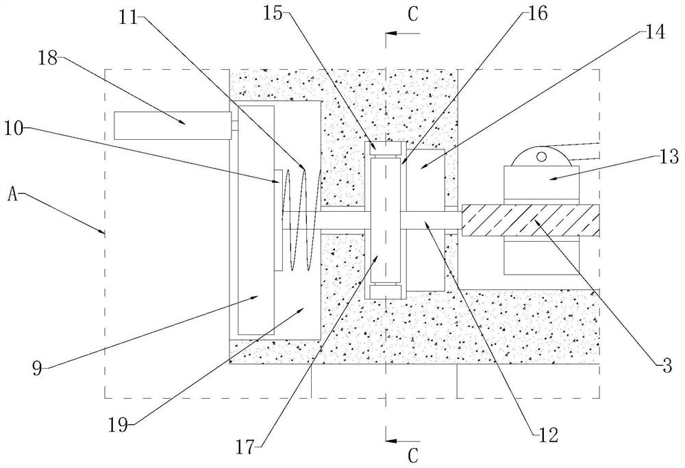
[0032] refer to Figure 1-5 , this embodiment specifically expounds the structure and implementation of the fixing mechanism on the basis of the first embodiment. The fixing mechanism includes a movable plate 10, a return spring 11, a rotation groove 14, a positioning gear ring 15, a positioning groove 16 and a positioning tooth disc 17. , the inner wall of the movable groove 19 is fixedly connected with a return spring 11, and the end of the return spring 11 is fixedly connected with a movable plate 10, and the side of the movable plate 10 away from the return spring 11 is in contact with the turntable 9, and the movable plate 10 is in contact with the return spring 11 Both are sleeved on the circumferential side wall of the rotating rod 12, and the interior of the platen 1 is provided with a rotating groove 14 and a positioning groove 16, and the rotating groove 14 and the positioning groove 16 are located between the installation groove 2 and the movable groove 19, and the r...


PUM


Abstract

The invention discloses a design table for development of a smart office OA system, and relates to the field of design tables. In allusion to the problems that the table top angle of an existing design table cannot be adjusted according to use requirements, design paper is not easy to fix, and the design efficiency is affected, the invention proposes the following scheme: the design table comprises a table plate, supporting columns are fixedly connected to the four corners of the bottom end of the table plate, a mounting groove is formed in the top end of the table plate, a design plate is rotatably mounted on the inner wall of one side of the mounting groove, a paper positioning mechanism is arranged on the front face of the design plate, a movable groove is formed in the side, which is close to the hinge point of the design plate, of the table plate, a rotating disc is rotatably mounted in the movable groove, and a handle perpendicular to the surface of the rotating disc is mounted on the surface of the rotating disc. The design table is novel in structure, the use angle of the design plate can be adjusted, the use requirements of different designers are met, meanwhile, design paper can be effectively fixed, the design efficiency is improved, and the design table is suitable for application and popularization.

Description

technical field [0001] The invention relates to the field of design desks, in particular to a design desk for the development of an intelligent office OA system. Background technique [0002] Software development is the process of building a software system or a software part of the system according to user requirements. Software development is a system engineering that includes requirement capture, requirement analysis, design, implementation and testing. Software is generally implemented using some programming language. Usually, software development tools can be used for development. Software is divided into system software and application software. [0003] When developing a smart office OA system, a design desk is required for design and development, while traditional design desks are set horizontally, causing designers to keep their heads down for a long time, causing physical discomfort, and traditional design desks cannot Fixing the design paper will reduce the de...

Claims


Application Information

Patent Timeline
Patent Type & Authority Applications(China)
IPC IPC(8): A47B21/013A47B97/02A47B97/00
CPCA47B21/00A47B97/02A47B97/00
Inventor 向军唐毅汤泽淋祝嵩
Owner 中通服供应链股份有限公司
Why Eureka
Try Eureka