Breaking machine

A crusher and casing technology, applied in the field of bulk crushers, can solve the problems of shortening the service life of blades 4-4, time-consuming downtime for replacement, and reducing crushing efficiency, so as to improve cutting and crushing efficiency and reduce the number of times of downtime to replace blades. , Improve the effect of crushing efficiency

Pending Publication Date: 2021-04-30
SHANDONG JIEFENG MACHINERY MFG
View PDF0 Cites 1 Cited by
  • Summary
  • Abstract
  • Description
  • Claims
  • Application Information

AI Technical Summary

Problems solved by technology

During the rotation of the rotor 4, once the corner of the cutting end of the blade 4-4 is damaged, for example, the corner of the cutting end of the blade 4-4 is broken by stones mixed in the material when cutting the material, and the blade 4-4 cannot continue to be used , which shortens the service life of the blade 4-4, and then requires time-consuming downtime to replace the blade 4-4, which not only reduces the crushing efficiency, but also increases the material cost

Method used


Image

  • Breaking machine
  • Breaking machine
  • Breaking machine

Examples


Embodiment

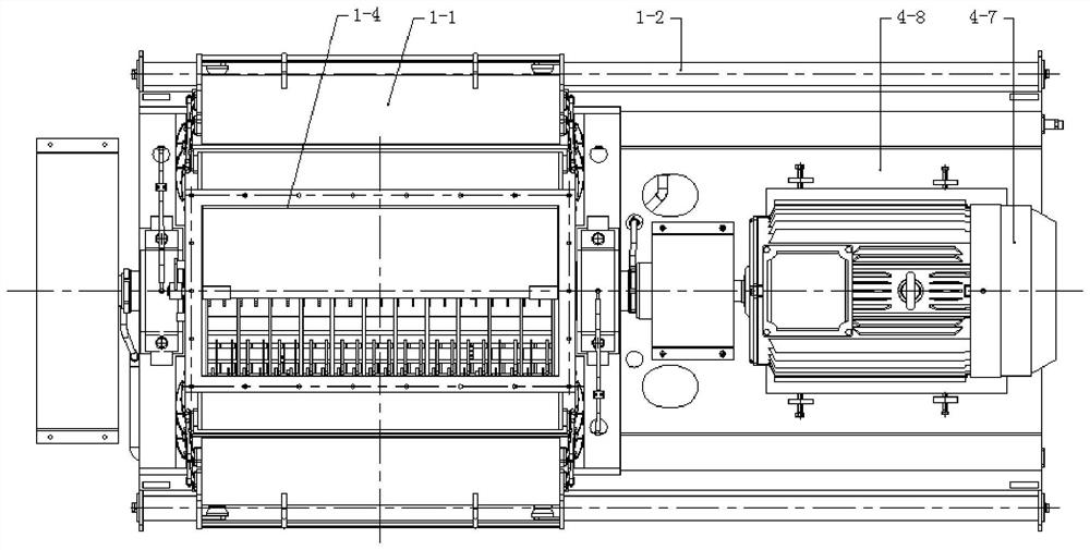
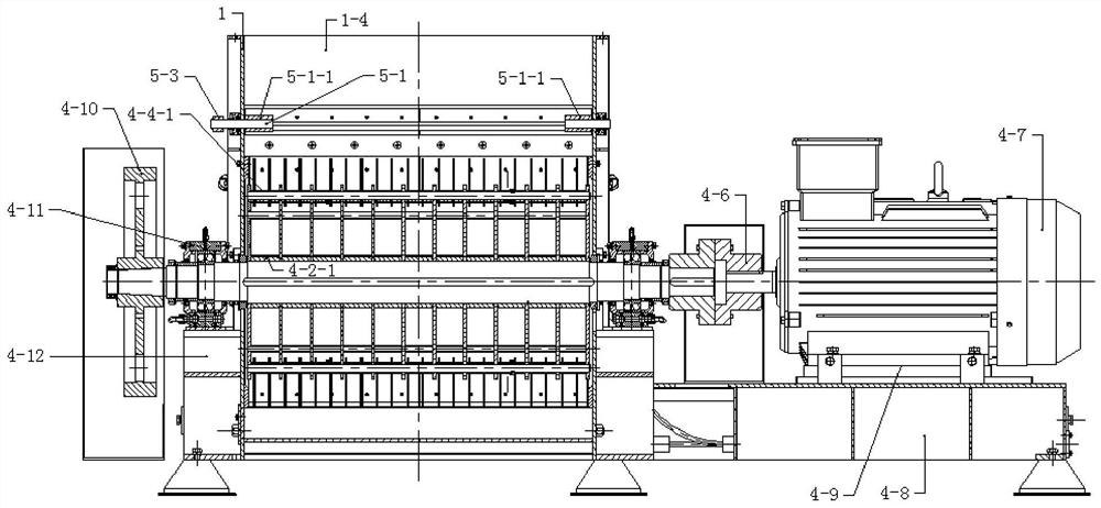
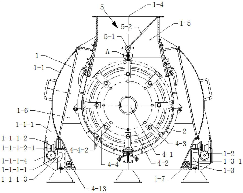
[0049] A chip breaker, comprising a casing 1. Such as image 3 As shown, the casing 1 can be placed directly on the ground without a base, thereby lowering the center of gravity of a kind of breaking machine of this embodiment, making the running of a kind of breaking machine of this embodiment more stable and reliable.

[0050] Such as image 3 As shown, the side wall of the casing 1 is provided with an operation door 1-1. The lower end of the casing 1 is fixed with a guide rod 1-2 and a limiting plate 1-3 by bolts, and the limiting plate 1-3 is provided with a limiting long groove 1-3-1 on a side away from the casing 1 . The lower end of the operating door 1-1 is welded with a slide plate 1-1-1, the slide plate 1-1-1 is provided with a guide hole 1-1-1-1, and the guide hole 1-1-1-1 cooperates with the guide rod 1-2 . Sliding seat 1-1-1-2 is welded on the sliding plate 1-1-1, and roller 1-1-1-2-1 is installed on the sliding seat 1-1-1-2, and roller 1-1-1-2 -1 is arranged...


PUM


Abstract

The invention discloses a breaking machine. The breaking machine comprises a machine shell, wherein an operation door is arranged on the side wall of the machine shell; a screen used for dividing an inner cavity of the machine shell into a breaking chamber and a collecting chamber is arranged in the machine shell; the breaking chamber is communicated with a feeding port formed in the upper end of the machine shell; the screen is connected with the machine shell through a screen pressing mechanism; a rotor is arranged in the breaking chamber and connected with the machine shell; the rotor comprises a rotor shaft, multiple cutter heads, multiple cutter shafts and multiple blades; the cutter heads are arranged on the rotor shaft; each cutter shaft is connected with all the cutter heads; all the cutter shafts are evenly distributed in the circumferential direction of the cutter heads; the blades are arranged on the portions, between every two adjacent cutter heads, of the cutter shafts; and multiple cutting teeth are arranged at the cutting ends of the blades. According to the breaking machine, the service life of the blades can be prolonged.

Description

technical field [0001] The invention relates to the technical field of breakers, in particular to a breaker. Background technique [0002] When using a crusher to crush waste paper and other materials, the rotor in the crusher is mainly used to cut and crush the materials. Existing rotor structures such as Figure 15 As shown, the rotor 4 includes a rotor shaft 4-1, a cutter head 4-2, a cutter shaft ( Figure 15 Not shown in), blade 4-4, a plurality of cutterheads 4-1 are installed on the rotor shaft 4-1, the cutter shaft is provided with a plurality of, each cutter shaft is connected with all cutter heads 4-2, all The cutter shafts are evenly distributed along the circumferential direction of the cutter heads 4-2, and blades 4-4 are arranged on the cutter shafts between two adjacent cutter heads 4-2. [0003] During the rotation of the rotor 4, if Figure 15 A corner of the cutting end of the blade 4-4 shown can cut the material, for example, in the process of the clockwis...

Claims


Application Information

Patent Timeline
Patent Type & Authority Applications(China)
IPC IPC(8): B02C18/14B02C18/18B02C23/14B02C18/24B02C18/22
CPCB02C18/0007B02C18/0084B02C18/14B02C18/184B02C18/2225B02C18/24B02C23/14B02C2018/0038B02C2201/06
Inventor 张吉祥王玉鹏苗海滨李英杰
Owner SHANDONG JIEFENG MACHINERY MFG
Why Eureka
Try Eureka