Improved indicator valve installation structure of medium-speed diesel engine

A diesel engine and indicator valve technology, applied in mechanical equipment, workpiece clamping devices, springs/shock absorbers, etc., can solve problems such as easy noise, easy damage, and inconvenient installation of indicator tubes, etc., to achieve increased friction , improve stability, and be beneficial to the effect of protection

Pending Publication Date: 2021-04-30
HUDONG HEAVY MACHINERY
View PDF0 Cites 1 Cited by
  • Summary
  • Abstract
  • Description
  • Claims
  • Application Information

AI Technical Summary

Problems solved by technology

[0004] Aiming at the deficiencies of the prior art, the present invention provides an improved installation structure of the indicator valve of the medium-speed diesel engine, which has the advantages of elastic fixing of the indicator tube and convenient installation, and solves the problems of the indicator valve of the medium-speed diesel engine in the prior art. The indicator tube is usually fixed by bolts through the arc-shaped clamp and the arc-shaped bracket. There are several defects in this method. First, the rigid contact between the clamp and the bracket and the indicator tube Extrusion is easy to cause damage. Secondly, because the diesel engine is prone to vibration during use, it causes the dynamometer tube in rigid contact with the clamp and the bracket to resonate, causing the dynamo tube, the clamp and the bracket to wear, and is prone to damage Noisy, and it is not conducive to the stability of the components on the power indicator valve. Finally, the arc grooves on the bracket and the clamp are fixed in position and cannot be fine-tuned, which is not convenient for the installation of the power indicator tube.

Method used


Image

  • Improved indicator valve installation structure of medium-speed diesel engine
  • Improved indicator valve installation structure of medium-speed diesel engine

Examples


Embodiment Construction

[0016] The following will clearly and completely describe the technical solutions in the embodiments of the present invention with reference to the accompanying drawings in the embodiments of the present invention. Obviously, the described embodiments are only some, not all, embodiments of the present invention. Based on the embodiments of the present invention, all other embodiments obtained by persons of ordinary skill in the art without making creative efforts belong to the protection scope of the present invention.

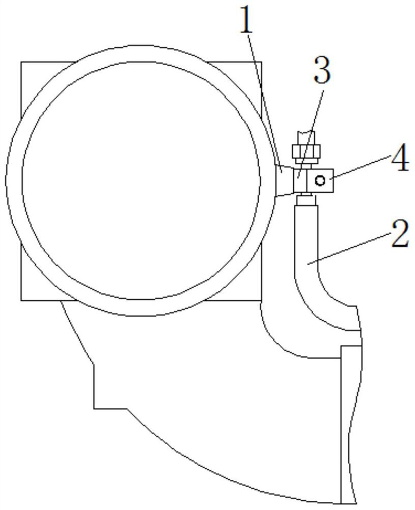
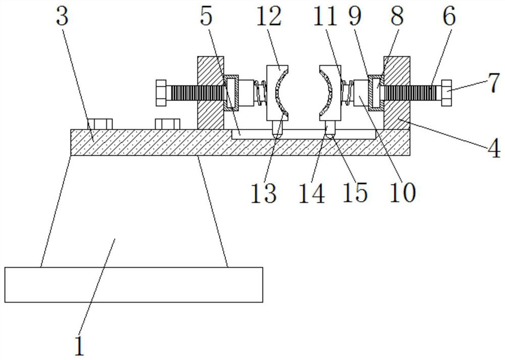
[0017] see Figure 1-2 , a kind of indicator valve installation improvement structure of medium-speed diesel engine, including boss 1 and indicator tube 2 on the A / B two rows of intake pipes on the diesel engine, the top of boss 1 is fixedly connected with bracket 3 by bolts, and the bracket One side of the top and the middle part of the top are all fixedly connected with a fixed frame 4, and the top of the inner cavity of the bracket 3 is provided with a chut...


PUM


Abstract

The invention relates to the technical field of diesel engine indicator valve installation, and discloses an improved indicator valve installation structure of a medium-speed diesel engine. The improved indicator valve installation structure comprises a boss and an indicator pipe which are positioned on two rows A/B of gas inlet pipes on the diesel engine. The top of the boss is fixedly connected with a support through bolts. Fixed frames are fixedly connected to one side of the top of the support and the middle of the top end of the support correspondingly. According to the improved indicator valve installation structure of the medium-speed diesel engine, by rotating threaded rods and adjusting the distance between two clamping frames, on one hand, the improved indicator valve installation structure can adapt to clamping and fixing of indicator pipes with different diameters, and on the other hand, the indicator pipes can be clamped conveniently; and meanwhile, the indicator pipes can be installed conveniently by adjusting the positions of the clamping frames. According to the installation structure, through cooperation of telescopic rods and springs, the clamping frames and the indicator pipe are elastically clamped and fixed, and therefore, the indicator pipe is subjected to buffering and vibration reduction through vibration generated in the use process of the diesel engine, vibration of the indicator pipe is reduced, and stability of the indicator pipe under the long-term use condition is facilitated.

Description

technical field [0001] The invention relates to the technical field of installation of a power indicating valve of a diesel engine, in particular to an improved installation structure of a power indicating valve of a medium-speed diesel engine. Background technique [0002] The indicator valve is installed on the cylinder head of the diesel engine. It has two functions: one is to flush out the impurities, residual water or oil accumulation in the cylinder from the indicator valve when the diesel engine is started, so as to judge whether there is any leakage in the cylinder. Oil or water; the second is to install the explosion pressure gauge to measure the cylinder explosion pressure so as to observe and judge the working condition of the diesel engine cylinder, calculate and analyze the working performance of the diesel engine, ensure the operation of the diesel engine in the best condition, and improve its economy, power and performance. reliability. [0003] However, the ...

Claims


Application Information

Patent Timeline
Patent Type & Authority Applications(China)
IPC IPC(8): B25B11/00F16F7/104
CPCB25B11/00F16F7/104
Inventor 龚俊杰洪宁玉王凯
Owner HUDONG HEAVY MACHINERY
Why Eureka
Try Eureka