Concrete member and pouring method thereof

A concrete and component technology, applied in the direction of building components, buildings, structural elements, etc., can solve problems such as breakage, deflection of horse stool, failure of support function, etc., to prevent deviation, save welding process, and simplify construction technology Effect

Inactive Publication Date: 2021-04-30
SHANGHAI BAOYE GRP CORP
View PDF12 Cites 0 Cited by
  • Summary
  • Abstract
  • Description
  • Claims
  • Application Information

AI Technical Summary

Problems solved by technology

[0004] However, the horse stool reinforcement of the conventional structure needs to be welded and fixed with the upper steel reinforcement, and the deflection and breakage of the horse stool reinforcement sometimes occur during the construction process, resulting in the failure of its supporting function

Method used


Image

  • Concrete member and pouring method thereof
  • Concrete member and pouring method thereof
  • Concrete member and pouring method thereof

Examples


no. 1 Embodiment

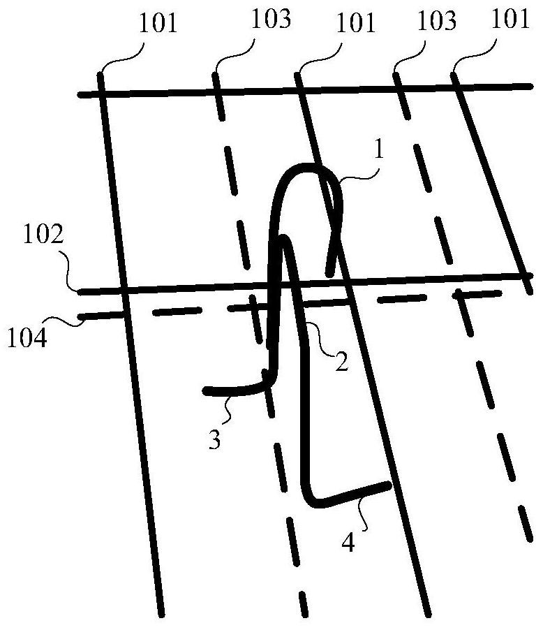
[0051] The first specific embodiment of the present invention provides a concrete member, which includes upper steel bars, lower layer steel bars and horse stool bars.

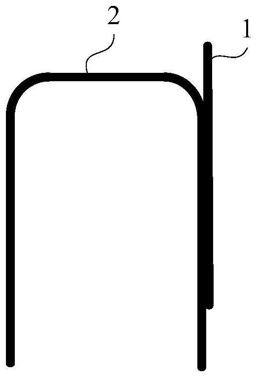
[0052] For details, please refer to Figure 2 to Figure 4 , the horse stool bar includes a positioning hook 1, a support bar 2, a first vertical strut, a second vertical strut, a first leg 3, and a second leg 4. in:

[0053] The positioning hook 1 is located on the top of the horse stool bar, and the opening of the positioning hook 1 is facing downward, and is used to hook down the first reinforcing bar unit 101 in the upper layer of reinforcing bars;

[0054] The support cross bar 2 is used to support the second steel bar unit 102 in the upper layer of steel bars. The second steel bar unit 102 is located below the first steel bar unit 101 and is perpendicular to the first steel bar unit 101. Therefore, the plane where the positioning hook is located and the support cross bar 2 vertical;

[0055] The first ...

no. 2 Embodiment

[0079] See Figure 5 , the second specific embodiment of the present invention provides a horse stool tendon, the difference between this horse stool tendon and the horse stool tendon in the above-mentioned first specific embodiment is only that: the bottom of the horse stool tendon can also be provided with a third leg 5 and the fourth leg 6. in:

[0080] The third leg 5 and the fourth leg 6 are located at the bottom of the first vertical strut and the second vertical strut respectively and are fixedly connected thereto. A vertical strut, the support cross bar 2, and the second vertical strut are located in the same vertical plane.


PUM


Abstract

The invention discloses a concrete member and a pouring method thereof. The concrete member comprises an upper-layer steel bar, a lower-layer steel bar and a split head bar; the split head bar comprises a positioning hook, a supporting cross rod, a first vertical supporting rod, a second vertical supporting rod, a first supporting foot and a second supporting foot, wherein the positioning hook is located at the top of the split head bar, an opening of the positioning hook faces downwards, and the positioning hook is used for hooking a first steel bar unit in the upper-layer steel bar downwards; the supporting cross rod is used for supporting a second steel bar unit in the upper-layer steel bar, and the second steel bar unit is located below the first steel bar unit and is perpendicular to the first steel bar unit; the first vertical supporting rod and the second vertical supporting rod are located below the two ends of the supporting cross rod correspondingly and are perpendicularly and fixedly connected with the supporting cross rod, and the first vertical supporting rod is fixedly connected with the positioning hook; the first supporting foot is located at the bottom of the first vertical supporting rod and is fixedly connected with the first vertical supporting rod; and the second supporting foot is located at the bottom of the second vertical supporting rod and is fixedly connected with the second vertical supporting rod. According to the concrete member and the pouring method thereof, the steel bars can be prevented from deviating and deforming through the split head bar.

Description

technical field [0001] The invention relates to the technical field of house construction, and in particular to a concrete component and a pouring method thereof. The concrete construction is provided with a horse stool bar for preventing deviation and deformation of steel bars. Background technique [0002] Horse stool, construction term. It is shaped like a stirrup, so it is called stirrup tendon, also known as supporting steel bar (iron horse). It is used in the middle of the upper and lower layers of steel bars to fix and support the upper layer of steel bars. The shape and structure of conventional horse stool bars are as follows: figure 1 As shown in , the top end is welded to the upper steel bar, and the lower end is supported on the lower steel bar. [0003] During the construction process such as pouring concrete, the upper steel bars are often deformed due to the trampling of workers. Therefore, the horse stool bar is indispensable as the measure reinforcement ...

Claims


Application Information

Patent Timeline
Patent Type & Authority Applications(China)
IPC IPC(8): E04C5/18E04B5/32E02D27/01
CPCE04C5/18E04B5/32E02D27/01E04B2103/02
Inventor 张杰熊航程红杰汪永陈连健
Owner SHANGHAI BAOYE GRP CORP
Why Eureka
Try Eureka