Cement surface trowelling device for partition construction

A cement and bottom surface technology, which is applied in the field of cement surface smoothing devices for partition construction, can solve problems such as wasting labor, affecting construction progress, and work cannot be carried out, and achieves the effects of high quality, improved functionality, and improved work efficiency

Inactive Publication Date: 2021-04-30
温州顺启建筑有限公司
View PDF11 Cites 2 Cited by
  • Summary
  • Abstract
  • Description
  • Claims
  • Application Information

AI Technical Summary

Problems solved by technology

[0002] During the construction of the courtyard, it is necessary to add a partition wall between the courtyard and the courtyard door, and decorate murals on the partition wall to make the courtyard beautiful. The outer wall of the partition wall made of bricks needs to be reinforced with cement first, and then used Ceramic tiles and murals are finally decorated on the wall. The cement reinforcement link is the most important. If the surface of the cement layer is uneven, it will lead to uneven mud surface, which will make the follow-up work impossible.
[0003] The existing construction method for scraping the cement layer is: manually hold a wooden board, paste it on the wall of the cement layer, and scrape it from top to bottom, so that the protruding cement layer is scraped downwards. Beginners use their arms unevenly It will lead to more uneven scraping layer, affect the construction progress, and waste labor, so there is an urgent need to design a functional device to improve work efficiency

Method used


Image

  • Cement surface trowelling device for partition construction
  • Cement surface trowelling device for partition construction
  • Cement surface trowelling device for partition construction

Examples


Embodiment Construction

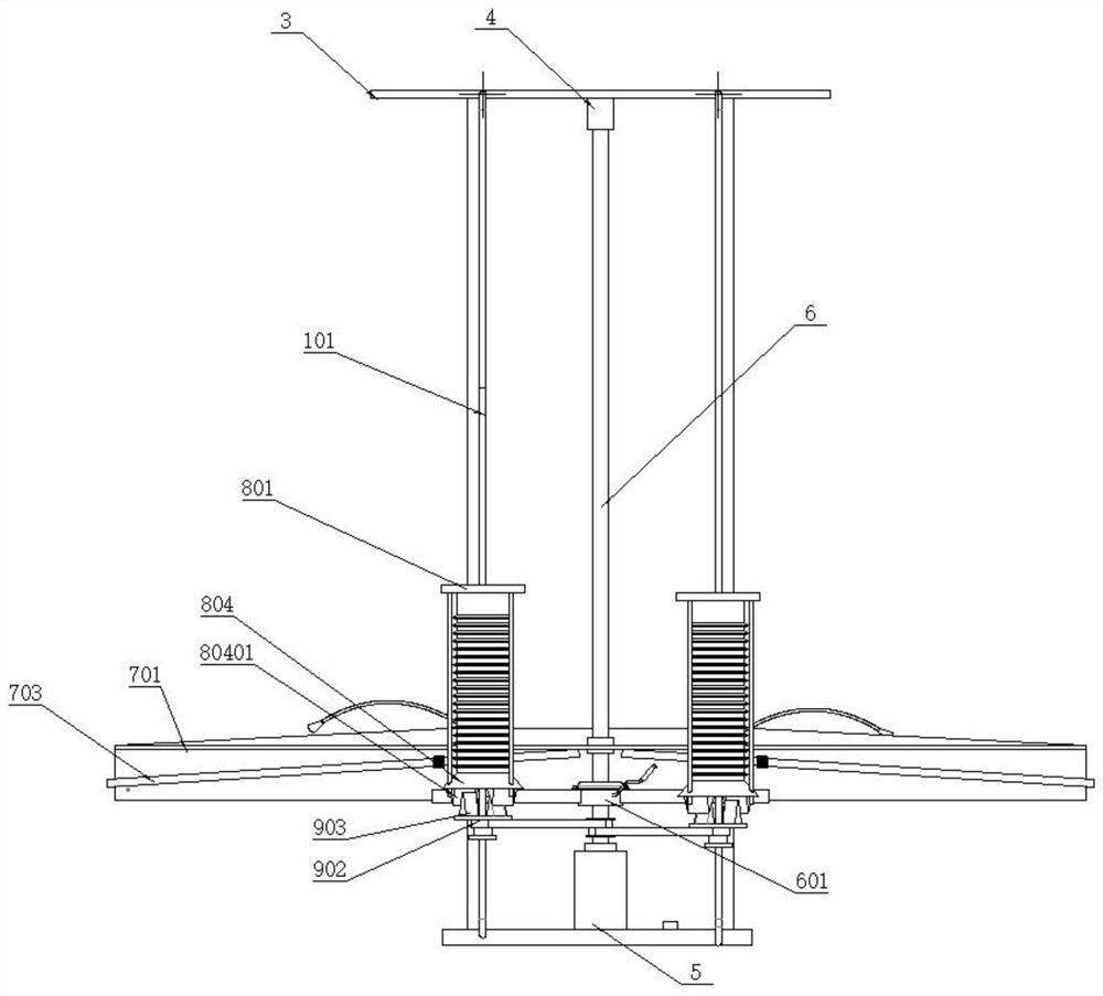
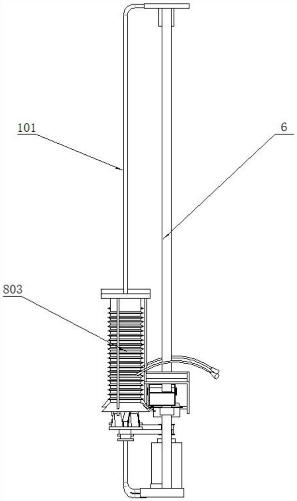
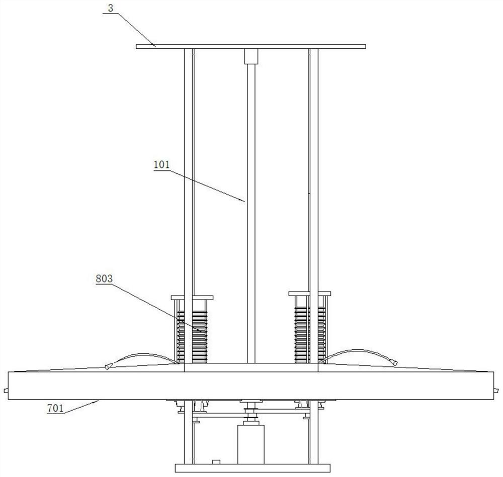
[0030] The following is a clear and complete description of the technical solution of the patent of the present invention in conjunction with the accompanying drawings. Apparently, the described embodiments are part of the embodiments of the present invention, not all of them. Based on the embodiments of the present invention, all other embodiments obtained by those skilled in the art without creative efforts fall within the protection scope of the present invention.

[0031] In the description of the present invention, it should be noted that if the terms "center", "upper", "lower", "left", "right", "vertical", "horizontal", "inner", "outer" appear The orientation or positional relationship indicated by etc. is based on the orientation or positional relationship shown in the drawings, and is only for the convenience of describing the present invention and simplifying the description, rather than indicating or implying that the referred device or element must have a specific or...


PUM


Abstract

The invention relates to a cement surface trowelling device for partition construction. The device comprises a bottom plate, a hand pipe, a limiting plate, a trowelling mechanism, an air seat mechanism, and a lifting mechanism; two large guide columns and a motor are arranged on the bottom plate; the top ends of the two large guide columns are connected through a top plate; a bearing seat is further installed on the bottom face of the top plate; a screw rod is arranged on an action shaft of the motor; the motor not only drives the screw rod to enable the trowelling mechanism to lift, but also is provided with the lifting mechanism between an action shaft of the motor and the air seat mechanism arranged at the front side of a lifting frame; and when the motor is electrified to work, the air seat mechanism is promoted to be compressed upwards by the air seat mechanism, so that air in an inner cavity of the air seat mechanism is discharged outwards. The discharged gas can be applied to cleaning the trowelling mechanism, so that a mud layer left on the rear surface of the trowelling mechanism during cement scraping is cleaned downwards. In order to improve the structural rationality of the trowelling mechanism, a scraper element discharges mud to the two sides when receiving and taking the mud falling off from a wall surface, and in actual use, supporting hoppers can be additionally arranged at the two sides to perfectly receive and take the mud.

Description

technical field [0001] The invention relates to the technical field of plastering building construction, in particular to a cement surface plastering device for partition construction. Background technique [0002] During the construction of the courtyard, it is necessary to add a partition wall between the courtyard and the courtyard door, and decorate murals on the partition wall to make the courtyard beautiful. The outer wall of the partition wall made of bricks needs to be reinforced with cement first, and then used Ceramic tiles and murals are finally decorated on the wall. Among them, the cement reinforcement link is the most important. If the surface of the cement layer is unevenly loaded, it will lead to uneven mud surface, which will make the follow-up work impossible. [0003] The existing construction method for scraping the cement layer is: manually hold a wooden board, paste it on the wall of the cement layer, and scrape it from top to bottom, so that the protru...

Claims


Application Information

Patent Timeline
Patent Type & Authority Applications(China)
IPC IPC(8): E04F21/08B08B5/02B08B3/02
CPCE04F21/08B08B5/02B08B3/02
Inventor 李玉辉孔虎
Owner 温州顺启建筑有限公司
Why Eureka
Try Eureka