Slurry lifting machine for building construction

A technology of building construction and lifting seats, which is applied in the direction of lifting devices, recycling technology, cleaning methods and appliances, etc., can solve the problems of low work efficiency and waste of manpower, and achieve the effects of saving labor, improving work efficiency and improving safety factor

Active Publication Date: 2021-01-22
广东旭峰建筑工程有限公司
View PDF10 Cites 1 Cited by
  • Summary
  • Abstract
  • Description
  • Claims
  • Application Information

AI Technical Summary

Problems solved by technology

[0003] During the above work process, workers need to climb to the top of the reinforcement cage, and manually pull the material hopper of the pulp lifter to drop the concrete into the reinforcement ca

Method used


Image

  • Slurry lifting machine for building construction
  • Slurry lifting machine for building construction
  • Slurry lifting machine for building construction

Examples


Embodiment Construction

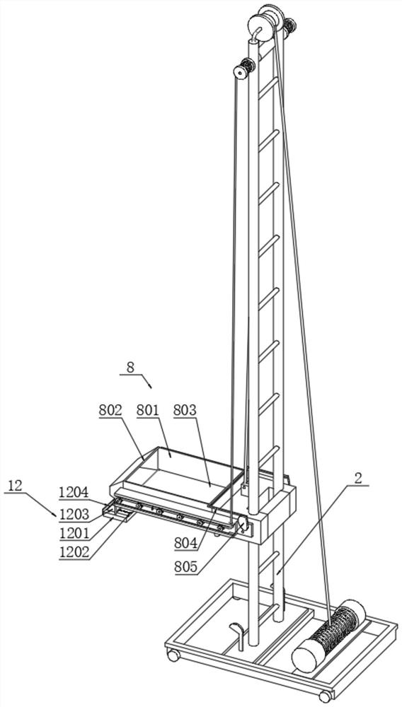
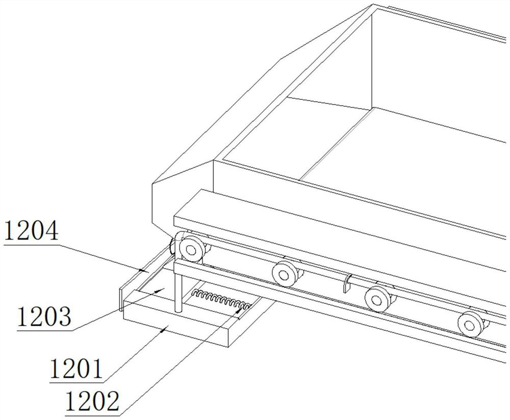
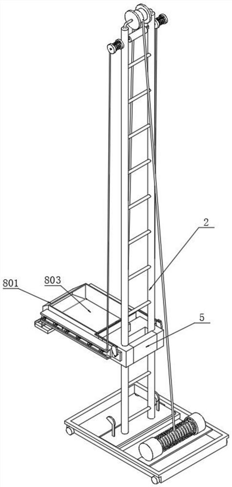
[0033] The following is attached figure 1 - Figure 11 , the specific implementation manner of the present invention will be further described in detail, so as to make the technical solution of the present invention easier to understand and grasp.

[0034] The pulp lifter for building construction includes a moving seat 1, a hopper mechanism 8, a guide seat mechanism 11 and a feeding mechanism 12: the front end of the lifting seat 5 is welded with a support frame 6, and the support frame 6 is hinged with a hopper mechanism 8 and a lifting frame 2 A top pulley 9 and a double-axis motor 10 are installed on the top of the top pulley 9. There is a first sling 901 connected between the electric hoist 4 and the lifting seat 5 over the top pulley 9. When the electric hoist 4 is powered on, the first sling 901 Pulling the lifting seat 5 drives the hopper mechanism 8 to slide up and down along the lifting frame 2 to meet the filling of mud inside the reinforcement cage of various heig...


PUM


Abstract

The invention relates to a slurry lifting machine for building construction, relates to the technical field of slurry lifting machines, and solves the problems that when an existing slurry lifting machine lifts concrete materials and throws the concrete materials into a reinforcement cage, manual operation is needed, so that high labor intensity is caused, and potential safety hazards exist. The slurry lifting machine for building construction comprises a moving seat, a hopper mechanism, a guide seat mechanism and a material beating mechanism, wherein a lifting frame is installed on the top surface of the moving seat; an electric hoist and a lifting seat are arranged on the lifting frame; a supporting frame is welded to the front end of the lifting seat; a first lifting rope connected between the electric hoist and the lifting seat is arranged on a top pulley in a transition mode; and when the electric hoist is powered on to work, the concrete materials are subjected to tamping treatment later through the material beating mechanism. Through the arrangement for the device, people do not need to climb to a higher position to tamp concrete, so that the working efficiency is increased,the labor force is saved, the operation process is safer and more reliable, a material beating hopper generates a vibration effect, and soil adhered to the bottom surface of the material beating hopper due to beating for the concrete is vibrated downwards through the vibration effect, so that the functionality is improved.

Description

technical field [0001] The invention relates to the technical field of a material lifter for building construction, and more specifically, relates to a lifter for building construction. Background technique [0002] During building construction, concrete columns, also known as columns made of reinforced concrete material, are poured on the building site. It is the most basic load-bearing member in various engineering structures such as houses, bridges, and hydraulic engineering. It is often used as the pillar of the floor, bridge pier, foundation column, tower and truss. In the process, it is also necessary to pour the concrete slurry into the reinforcement cage forming frame by using the slurry lifter to pour. [0003] During the above work process, workers need to climb to the top of the reinforcement cage, and manually pull the material hopper of the pulp lifter to drop the concrete into the reinforcement cage, and then beat the concrete with a beating board to make the ...

Claims


Application Information

Patent Timeline
IPC IPC(8): B66F9/07B66F9/075B66F9/19B08B7/02B08B7/04
CPCB66F9/07B66F9/07504B66F9/195B08B7/04B08B7/02Y02W30/64
Inventor 唐健森孙亚茜
Owner 广东旭峰建筑工程有限公司
Why Eureka
Try Eureka