Supercharge Your Innovation With Domain-Expert AI Agents!

Adjusting type track lamp

An adjustment type, track technology, applied in lighting devices, lighting device parts, lighting auxiliary devices, etc., can solve the problems of high risk factor, difficulty in manual light adjustment, limitations of applicability and practicability, etc.

Pending Publication Date: 2021-04-30
GUANGDONG KANG CAI LIGHTING TECH CO LTD
View PDF0 Cites 0 Cited by
  • Summary
  • Abstract
  • Description
  • Claims
  • Application Information

AI Technical Summary

Problems solved by technology

[0002]Track light fixture is a common light fixture, which is mainly composed of a drive box installed in the track and a pole arranged on the bottom of the drive box, and the pole is connected with the pole through a pin. The shafts are connected to the lamp body, which is equipped with pulleys on the symmetrical side of the drive box. When in use, the drive box snaps in from both ends of the track. Currently, the mainstream of track lamps on the market is manual adjustment of the lamp. After the lamp is installed If the internal layout changes, it is difficult to manually adjust the lighting, and even the ceiling has to be re-arranged. The adjustment range of the beam angle of the lamps on the market is relatively small, generally within the range of 20-30 degrees, and it is still manual. For the installation of super high-rise ceiling lamps, the adjustment cost High, difficult, and dangerous
Although it can meet the needs of the market, the track lights of the prior art are not only inconvenient to install into the track body, but also the lighting direction is fixed and cannot be adjusted, so the applicability and practicability are limited to a certain extent

Method used


Image

  • Adjusting type track lamp
  • Adjusting type track lamp
  • Adjusting type track lamp

Examples


Embodiment 1

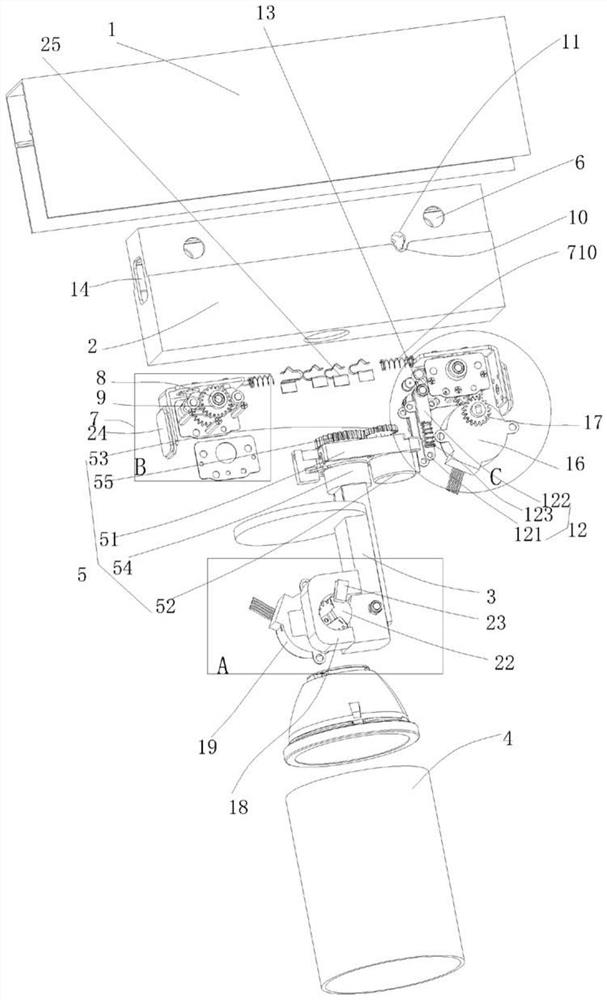
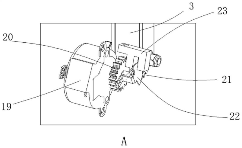
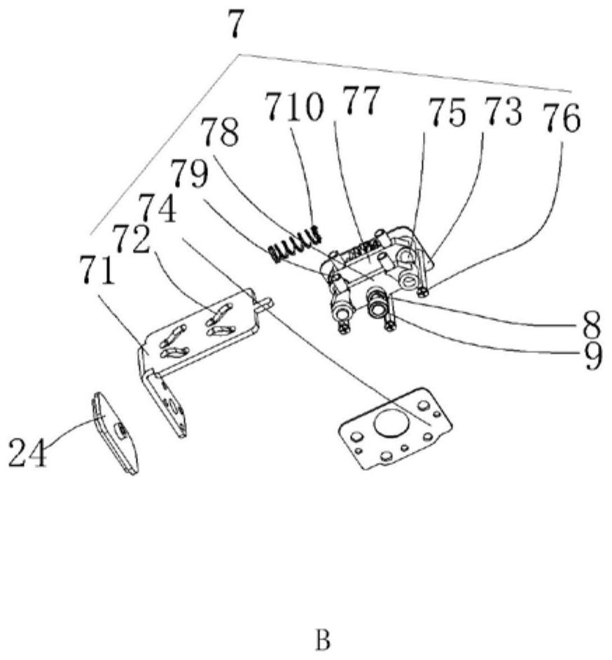
[0019] Figure 1 to Figure 4 A specific embodiment of the invention is shown in which figure 1 It is a structural schematic diagram of the present invention; figure 2 for figure 1 Schematic diagram of structure disassembly at A; image 3 for figure 1 Schematic diagram of structure disassembly in B; Figure 4 for figure 1 Schematic diagram of the disassembly of the structure at C. In this embodiment, the directional words such as left and right are only for convenience of description, and are not limited thereto.

[0020] See Figure 1 to Figure 4 , an adjustable track lamp, including a drive box 2 installed in the track 1, a drive circuit board is fixed in the drive box (the structure of the prior art, so it is not described in detail, but simply applied), so The mobile phone APP control module is arranged on the driving circuit board, the conductive shrapnel 25 is fixed on the top of the driving box, the pole 3 arranged under the driving box, and the lamp body 4 conn...


PUM


Abstract

The invention discloses an adjusting type track lamp, which comprises a driving box installed in a track; a driving circuit board is fixed in the driving box; a conductive shrapnel is fixed at the top of the driving box; a lamp body is connected with a supporting rod through a pin shaft; a rotating structure arranged in the driving box; pulley holes are arranged at the two ends of the side wall of the driving box respectively; pulley adjusting support structures are arranged at the two ends of an inner cavity of the driving box respectively; pulley shaft rods are fixed to the pulley adjusting support structures; pulleys are fixed to the pulley shaft rods; vertical positioning groove holes are further arranged on the side wall of the driving box; circular through holes are arranged at the top ends of the vertical positioning groove holes; locking structures are arranged in the driving box; and positioning pulleys are arranged in the locking structures. The adjusting type track lamp provided by the invention is reasonable in structural arrangement, the lamp body can be rotated as required, the pulleys can extend out of or retract into the driving box through the pulley adjusting support structures, mounting operation of the driving box and the track is facilitated, the driving box can be positioned in the track, and the applicability is strong and the practicability is good.

Description

technical field [0001] The invention belongs to the technical field of lighting lamps, and in particular relates to an adjustable track lamp. Background technique [0002] Track lamp is a common lamp, which is mainly composed of a drive box installed in the track, a pole arranged on the bottom of the drive box, and a lamp body connected to the pole through a pin shaft. It is on the symmetrical side of the drive box. It is equipped with pulleys. When in use, the drive box snaps in from both ends of the track. Currently, the mainstream of track lights on the market is manual light adjustment. If the internal layout of the light fixture is changed after installation, it is difficult to manually adjust the light, and even the ceiling has to be rebuilt. Layout, the light beam adjustment range of the lamps on the market is relatively small, generally within the range of 20-30 degrees, and it is still manual. For super high-rise ceiling lamps, the adjustment cost is high, the diffi...

Claims


Application Information

Patent Timeline
Patent Type & Authority Applications(China)
IPC IPC(8): F21V21/34
CPCF21V21/34
Inventor 谢伟雄
Owner GUANGDONG KANG CAI LIGHTING TECH CO LTD
Features
  • R&D
  • Intellectual Property
  • Life Sciences
  • Materials
  • Tech Scout
  • Unparalleled Data Quality
  • Higher Quality Content
  • 60% Fewer Hallucinations
Learn More