

Universal portable safety protection combined device for high-low voltage metering box
A safety protection and combined device technology, applied in the field of metering boxes, can solve problems such as unsatisfactory protection effects, and achieve the effects of being easy to carry and move, improving protection effects, and high resource utilization
- Summary
- Abstract
- Description
- Claims
- Application Information
AI Technical Summary
Problems solved by technology
Method used
Image

Examples
Embodiment Construction
[0023] The following will clearly and completely describe the technical solutions in the embodiments of the present invention with reference to the accompanying drawings in the embodiments of the present invention. Obviously, the described embodiments are only some, not all, embodiments of the present invention. Based on the embodiments of the present invention, all other embodiments obtained by persons of ordinary skill in the art without making creative efforts belong to the protection scope of the present invention.
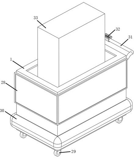
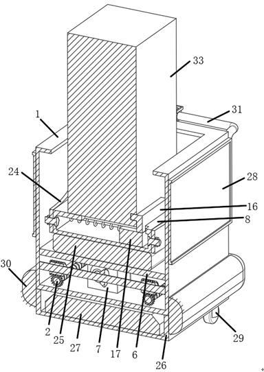
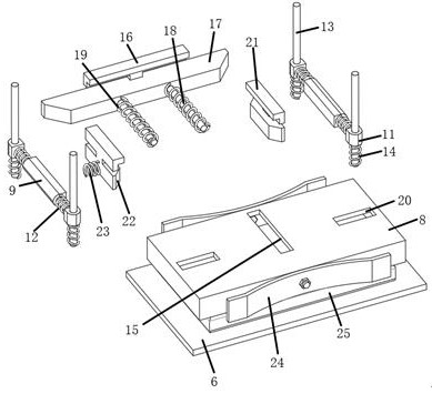
[0024] refer to Figure 1-5 , a general-purpose portable safety protection combination device for high and low pressure metering boxes, including a protective box 1, both sides of the bottom of the inner wall of the protective box 1 are rotationally connected, and a double-threaded screw 2 is provided, and both sides of the surface of the double-threaded screw 2 are threaded. Lifting moving block 3 is provided, and the top of lifting moving block 3 is all rota...
PUM
 Abstract
Description
Claims
Application Information