A kind of sandy wastewater purification joint for building floor
A waste water purification and floor technology, applied in chemical instruments and methods, separation methods, filtration and separation, etc., can solve the problems of inconvenient sand collection, time-consuming and manpower consumption, and achieve the effect of reducing time-consuming and rapid filtration
- Summary
- Abstract
- Description
- Claims
- Application Information
AI Technical Summary
Problems solved by technology
Method used
Image

Examples
Embodiment 1
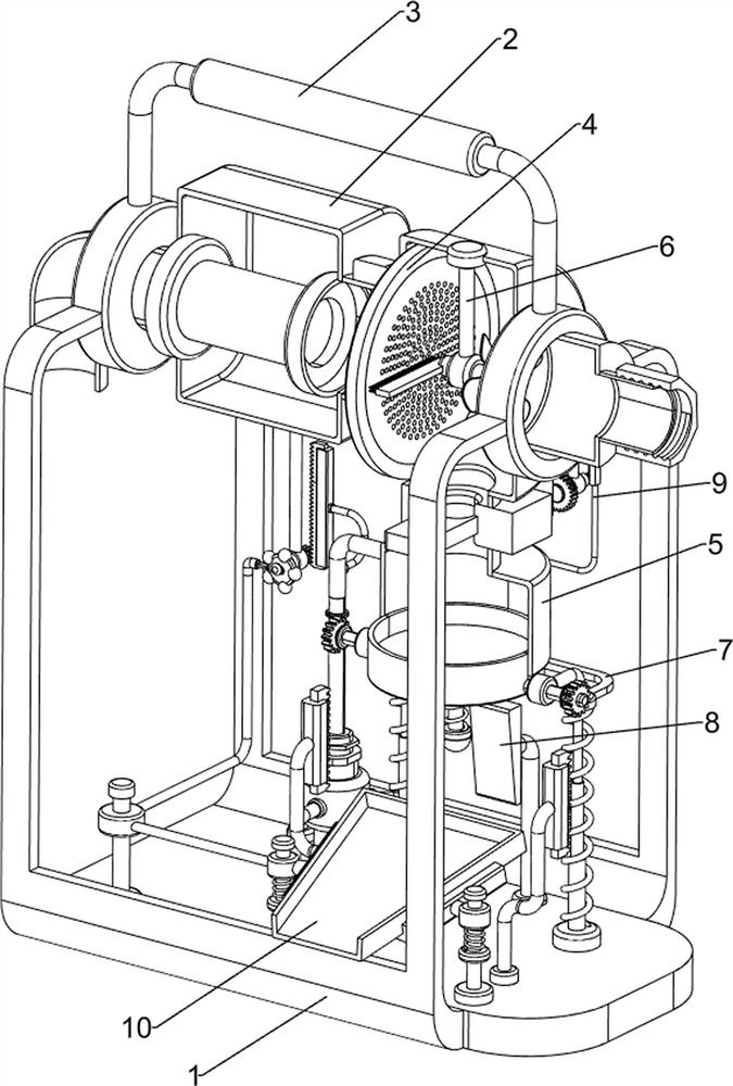
[0081] A sandy wastewater purification joint for building floors, such as figure 1 and figure 2 As shown in the figure, it includes a mounting frame 1, a box body 2, a handle 3, a filter mechanism 4 and a discharging mechanism 5. A box body 2 is arranged between the left and right sides of the mounting frame 1, and a box body 2 is arranged between the left and right sides of the top of the mounting frame 1. A handle 3 is provided, a filter mechanism 4 is provided between the mounting frame 1 and the box body 2 , and a discharge mechanism 5 is provided at the bottom of the box body 2 .
[0082] When people need to purify the waste water, they manually pull the handle 3 to move up, so that the mounting frame 1 and the box body 2 move upward, and then place the mounting frame 1 and the box body 2 beside the water pipe, and when people release the handle 3 At this time, people manually connect the water pipe to the filter mechanism 4, so that the sand-containing wastewater in th...
Embodiment 2
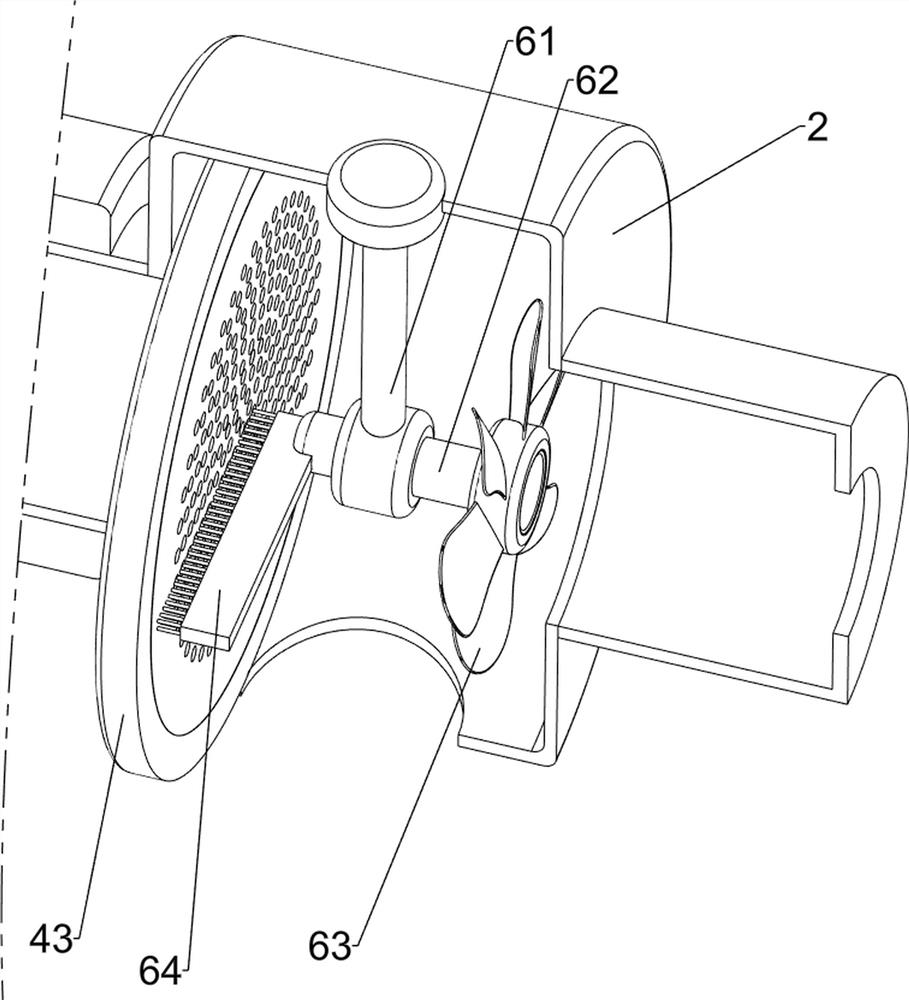
[0084] On the basis of Example 1, as image 3 As shown, the filter mechanism 4 includes a water inlet 41, a connection nut 42, a filter plate 43, an activated carbon filter element 44 and a water outlet 45, the right side of the box body 2 is connected with a water inlet 41, and the water inlet 41 is provided with a connection nut 42. A filter plate 43 is arranged in the middle of the body 2 , an activated carbon filter element 44 is arranged on the left side of the box body 2 , and a water outlet 45 is connected to the left side of the box body 2 .
[0085] When people place the mounting frame 1 and the box body 2 beside the water pipe, people manually connect the water pipe through the connection nut 42, and then the waste water enters the box body 2 through the water inlet 41. Due to the high fluidity of the sandy waste water, The sand-containing waste water is filtered through the filter plate 43 to filter the sand. At this time, the sand is filtered to the discharge mecha...
Embodiment 3
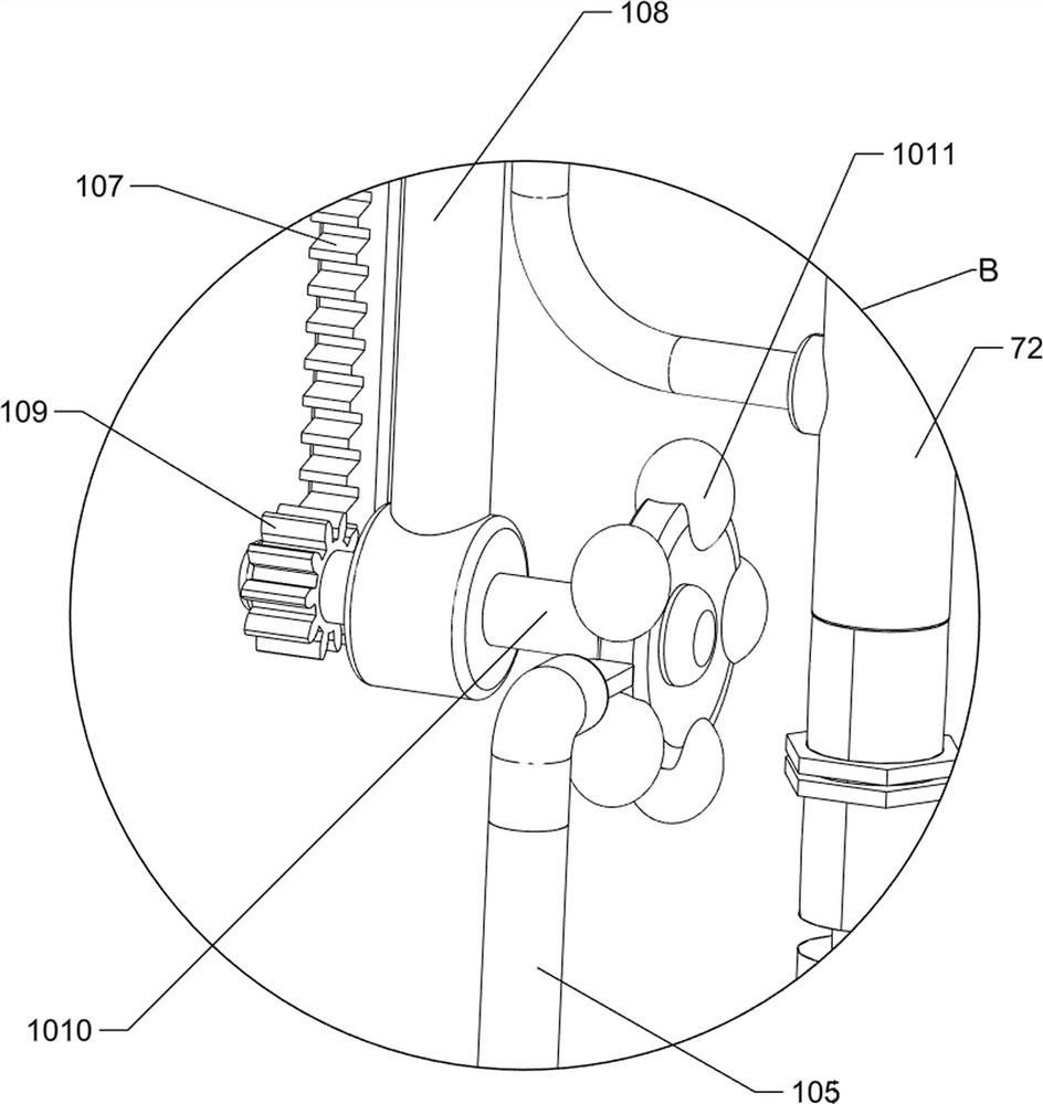
[0087] On the basis of Example 2, as figure 1 , figure 2 , Figure 4 , Figure 5 , Image 6 , Figure 7 , Figure 8 , Figure 9 , Figure 10 and Figure 11 As shown, the discharging mechanism 5 includes a sand box 51, a bottom cover 52, a valve body 53, a block 54, a bolt 55 and a threaded seat 56, and a valve body 53 is connected to the bottom of the right side of the box body 2, and the valve body 53 slides inside The valve body 53 is provided with a block 54, the bottom of the valve body 53 is provided with a sand box 51, the bottom cover 52 is slidably provided on both sides of the bottom of the sand box 51, and a bolt 55 is slidably provided in the valve body 53, and the bolt 55 is connected with the stopper. The block 54 is connected, and a threaded seat 56 is provided on the rear side of the valve body 53 , and the threaded seat 56 is connected with the bolt 55 in a rotational manner.
[0088] When the filter plate 43 filters the sand between the box body 2 an...
PUM
 Abstract
Description
Claims
Application Information
 - R&D
- Intellectual Property
- Life Sciences
- Materials
- Tech Scout
- Unparalleled Data Quality
- Higher Quality Content
- 60% Fewer Hallucinations
Browse by: Latest US Patents, China's latest patents, Technical Efficacy Thesaurus, Application Domain, Technology Topic, Popular Technical Reports.
© 2025 PatSnap. All rights reserved.Legal|Privacy policy|Modern Slavery Act Transparency Statement|Sitemap|About US| Contact US: help@patsnap.com