an optical detection system

A technology of optical detection and detection station, which is applied in the direction of material analysis, measuring device, scientific instrument, etc. by optical means, can solve the problems of inability to realize automatic loading and unloading detection, inaccurate positioning of loading PCB, and high labor cost. Improve work efficiency, reduce labor costs, and reduce labor intensity

Active Publication Date: 2022-07-26
SUZHOU VEGA TECH CO LTD
View PDF7 Cites 0 Cited by
  • Summary
  • Abstract
  • Description
  • Claims
  • Application Information

AI Technical Summary

Problems solved by technology

The existing PCB optical inspection system cannot realize automatic loading and unloading inspection, and there is inaccurate positioning of the loading PCB, and manual assistance is required, the inspection efficiency is low, and the labor cost is high

Method used


Image

  • an optical detection system
  • an optical detection system
  • an optical detection system

Examples


Embodiment Construction

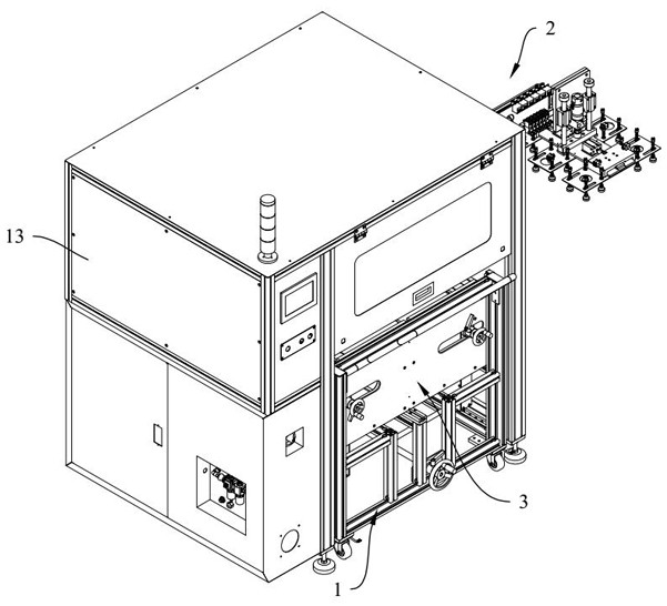
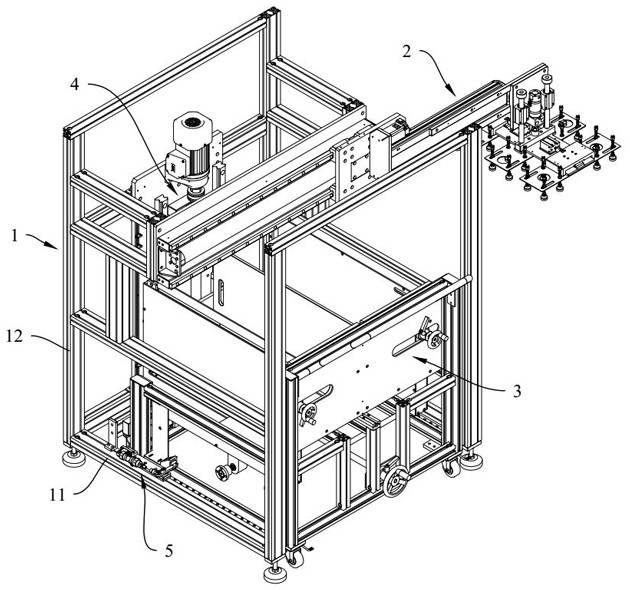
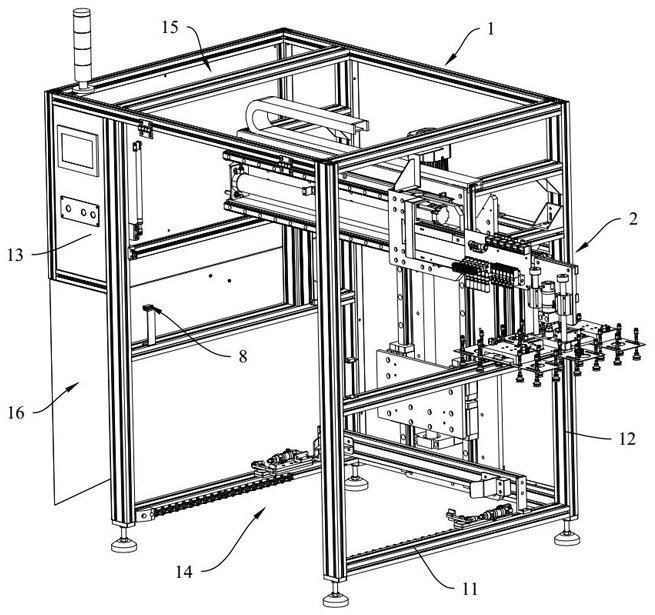
[0051] In order for those skilled in the art to better understand the technical solutions of the present invention, the technical solutions of the present invention are further described below with reference to the accompanying drawings and through specific embodiments.

[0052] In the description of the present invention, unless otherwise expressly specified and limited, the terms "connected", "connected" and "fixed" should be understood in a broad sense, for example, it may be a fixed connection, a detachable connection, or an integrated ; It can be a mechanical connection or an electrical connection; it can be a direct connection or an indirect connection through an intermediate medium, and it can be the internal connection of two elements or the interaction relationship between the two elements. For those of ordinary skill in the art, the specific meanings of the above terms in the present invention can be understood in specific situations.

[0053] In the description of t...


PUM


Abstract

The present invention relates to the technical field of optical detection equipment, in particular to an optical detection system. The optical detection system provided by the present invention includes an optical detection device, an automatic feeding device, an automatic feeding device and an automatic control system. The optical detection device is used for optical detection of materials; the automatic feeding device and the automatic feeding device are respectively arranged in the optical Both sides of the detection device; the automatic control system is used to control the automatic feeding equipment, the optical detection device and the automatic unloading equipment for automatic operation; the automatic feeding equipment and the automatic unloading equipment include the body, the loading and unloading mechanism, the material transfer mechanism and Positioning device, the material transfer mechanism is used to load and transfer materials, the loading and unloading mechanism is used to grab and transfer materials, and the material transfer mechanism can be detachably arranged in the body; the positioning device is used to lock the material transfer mechanism in a predetermined position in the body , so as to realize the positioning of materials without manual assistance, reduce labor costs and improve operating efficiency.

Description

technical field [0001] The present invention relates to the technical field of optical detection equipment, in particular to an optical detection system. Background technique [0002] During the optical inspection of the PCB board, the PCB needs to be moved to an optical inspection device for inspection. The existing PCB optical detection system cannot realize automatic loading and unloading detection, and the positioning of the loading PCB is inaccurate, and manual assistance is required, the detection efficiency is low, and the labor cost is high. [0003] Therefore, there is an urgent need for an optical detection system to solve the above problems. SUMMARY OF THE INVENTION [0004] The purpose of the present invention is to provide an optical detection system, which can realize automatic loading and unloading, improve loading and unloading efficiency and detection efficiency, and reduce labor costs. [0005] To achieve the above purpose, the following technical solut...

Claims


Application Information

Patent Timeline
Patent Type & Authority Patents(China)
IPC IPC(8): B07C5/34B07C5/02B07C5/36G01N21/956
CPCB07C5/34B07C5/02B07C5/362B07C5/361G01N21/956G01N2021/95638
Inventor 陈林锋高亮管凌乾常远
Owner SUZHOU VEGA TECH CO LTD
Why Eureka
Try Eureka