
A brake caster

A caster, brake block technology, applied in the direction of casters, wheels, vehicle parts, etc., can solve the problems of poor braking effect and complex structure of the braking device, and achieve the effects of good braking effect, simple structure and convenient braking operation.

Active Publication Date: 2022-05-13
宁波科盛万向轮有限公司
View PDF0 Cites 0 Cited by
  • Summary
  • Abstract
  • Description
  • Claims
  • Application Information

AI Technical Summary

Problems solved by technology

[0003] The invention overcomes the disadvantages of complex structure and poor braking effect of the existing brake device on the caster, and provides a brakeable caster. The brake device on the caster has a simple structure and good braking effect

Method used


Image

  • A brake caster
  • A brake caster
  • A brake caster

Examples


Embodiment 1

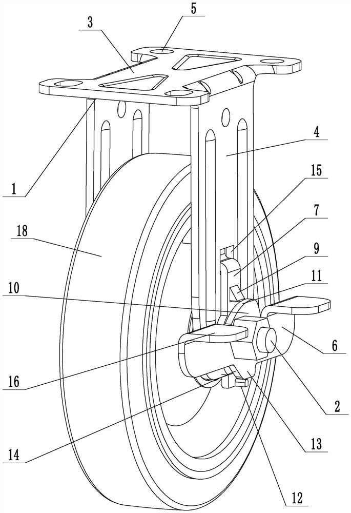
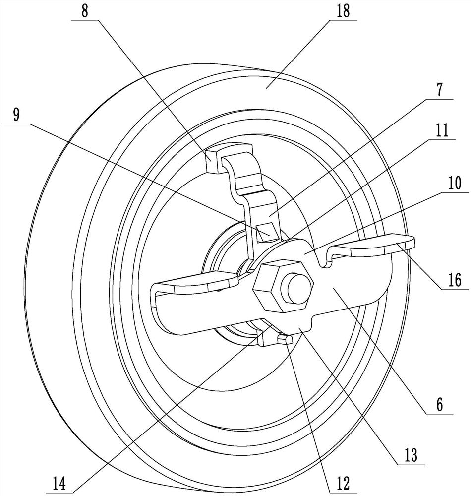
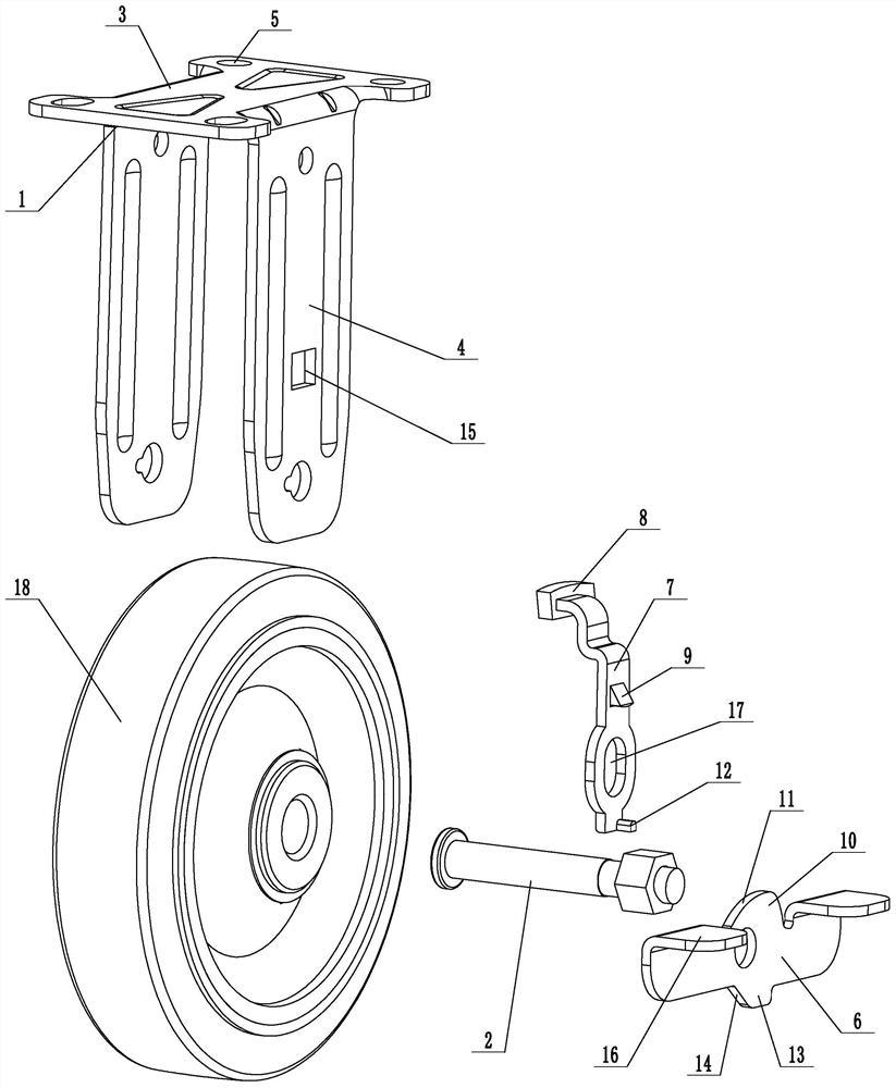
[0023] Embodiment 1: a kind of brake caster (see attached figure 1 , attached figure 2 , attached image 3 ), including a mounting frame 1 and a roller 18, the mounting frame is connected with the mounting shaft 2, and the rolling wheel is rotated and installed on the mounting shaft. The mounting frame includes a mounting plate 3 and two side plates 4. The two side plates are placed on both sides of the mounting plate to form an inverted U-shaped structure, and the mounting shaft is connected between the two side plates. Mounting holes 5 are provided at the corners of the mounting plate.

[0024] Rotate and install the brake pedal 6 on the installation shaft, the liftable lifting rod 7 is installed on the mounting frame, the lifting rod upper end is placed on the inside of the mounting frame, the lower end of the lifting rod is placed on the outside of the mounting frame, and the brake block 8 is installed on the lifting rod end. Be provided with upper top projection 9, an...

Embodiment 2

[0027] Embodiment 2: a kind of brake caster (see attached Figure 4 , attached Figure 5 ), its structure is similar to that of Embodiment 1, the main difference is that in this embodiment, the lifting rod is provided with a mounting cavity 19, and a locking column 20 that can move radially along the roller is installed in the mounting cavity, and the locking column extends out of the brake block , a brake pad 21 is installed on the upper end of the locking column, and a return spring 22 is installed in the installation cavity. The locking column is in an inverted T-shaped structure, and the brake block is provided with a through hole. The surface abuts on the positioning ring, and the return spring abuts between the installation cavity and the locking post.

[0028] Several locking holes 24 are evenly distributed on the inner wall of the roller, and the locking posts can be inserted into the locking holes. The surface of the brake block near the inner wall of the wheel is p...


PUM


Abstract

The invention discloses a brakeable caster wheel, which aims to solve the problems of complex structure and poor braking effect of the existing brake device on the caster wheel. The invention includes a mounting frame and a roller, the mounting frame is connected with a mounting shaft, the rolling wheel is rotated and mounted on the mounting shaft, a brake pedal is mounted on the mounting shaft, a liftable lifting rod is installed on the mounting frame, brake blocks are installed at the end of the lifting rod, and the lifting The rod is provided with an upper protrusion, and the brake pedal is provided with a top plate. With the rotation of the brake pedal, the top plate abuts on the upper protrusion and pushes the elevating rod to move upward so that the brake block abuts against the inner wall of the roller to realize braking. The brake device on the caster has simple structure, convenient brake operation and good brake effect.

Description

technical field [0001] The present invention relates to a wheel, more particularly, it relates to a brakeable caster. Background technique [0002] At present, the application fields of casters are very broad, such as trolleys, baby carriages, and various mobile devices are equipped with casters. The installation of casters facilitates movement and reduces resistance during movement. In order to ensure the stability after parking, many casters have a brake function, and the brakes of the casters can be realized after parking. However, the structure of the brake device on many casters is complicated, and the braking effect is not good. Contents of the invention [0003] The invention overcomes the disadvantages of complex structure and poor braking effect of the existing brake device on the caster, and provides a brakeable caster. The brake device on the caster has a simple structure and good braking effect. [0004] In order to solve the above technical problems, the pre...

Claims


Application Information

Patent Timeline
Patent Type & Authority Patents(China)
IPC IPC(8): B60B33/00
CPCB60B33/0078
Inventor 吴技科
Owner 宁波科盛万向轮有限公司
Learn More