
Equipment for producing high-quality and less-dust cement

A high-quality, cement-based technology, applied in the field of cement equipment, can solve the problems that cement powder is difficult to pass through the discharge port at the lower end, and the cement powder accumulates and is discharged.

Inactive Publication Date: 2021-05-04
李秋源
View PDF0 Cites 0 Cited by
  • Summary
  • Abstract
  • Description
  • Claims
  • Application Information

AI Technical Summary

Problems solved by technology

[0003] Since the cement powder is relatively fine, and the dust-less cement precipitation storage tank is placed vertically, so that the internal cement powder accumulates more, and when it is placed for a long time, it is easy to compact the cement powder at the bottom, resulting in less The cement powder inside the dust cement precipitation storage tank will be difficult to discharge through the discharge port at the lower end

Method used


Image

  • Equipment for producing high-quality and less-dust cement
  • Equipment for producing high-quality and less-dust cement
  • Equipment for producing high-quality and less-dust cement

Examples


Embodiment 1

[0026] For example figure 1 -example Figure 5 Shown:

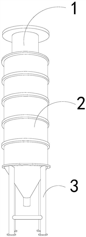
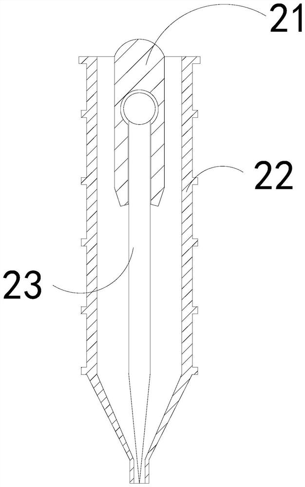
[0027] The present invention provides an equipment for producing high-quality dust-less cement, the structure of which includes a feed pipe 1, a cement tank 2, and a base bracket 3, the feed pipe 1 is embedded in the upper end of the cement tank 2, and the cement tank 2 Welded with the base bracket 3; the cement tank 2 includes a solid plate 21, a tank body 22, and a breaking mechanism 23, and the solid plate 21 and the tank body 22 are an integrated structure, and the breaking mechanism 23 and the center The fixed plate 21 is movable and engaged.

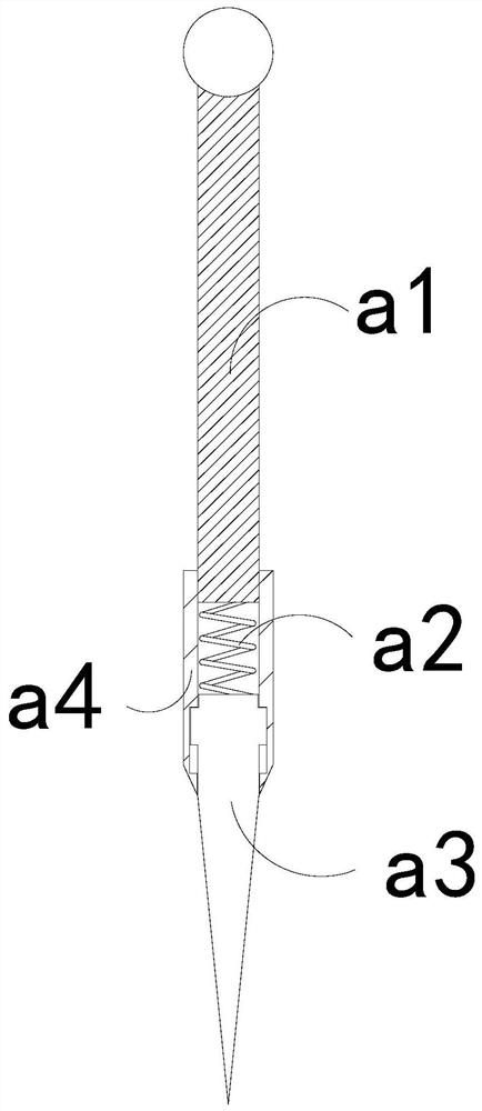
[0028] Wherein, the dispersing mechanism 23 includes an connecting rod a1, an elastic strip a2, a lower stretching plate a3, and a guide frame a4, the elastic strip a2 is installed between the connecting rod a1 and the lower stretching plate a3, and the lower stretching plate a3 Engaged with the pedestal a4, the pedestal a4 and the connecting rod a1 are an integrated struct...

Embodiment 2

[0034] For example Image 6 -example Figure 8 Shown:

[0035] Wherein, the overhanging block a34 includes a sealing plate c1, a booster ring c2, and a solid plate c3. The sealing plate c1 is embedded in the outer position of the booster ring c2. Embedded connection, the sealing plate c1 is provided with two, and evenly distributed symmetrically on the upper and lower sides of the solid plate c3, through the booster ring c2 can generate a continuous outward thrust on the sealing plate c1.

[0036] Wherein, the central solid plate c3 includes a frame c31, an extra push bar c32, an impact block c33, and a front plate c34. c31 is movable and engaged, the front plate c34 is embedded and fixed on the left side of the frame c31, the impact block c33 is made of alloy steel with high density, and the impact block c33 can follow the forward inertial force of the object to the front The impact is generated on the inner side of the plate c34.

[0037] Wherein, the front panel c34 inc...


PUM


Abstract

The invention discloses equipment for producing high-quality and less-dust cement. The equipment structurally comprises a feeding pipe, a cement tank and a base bracket, the feeding pipe is embedded and fixed at the upper end of the cement tank, the cement tank is welded with the base bracket, and an outer swing plate can swing outwards along a combination rod through a throwing force generated by rotation of a scattering mechanism, so that the outer swing plate can be matched with an outer extending block to scatter cement powder on the lower layer, so that the cement powder in the cement tank can be easily discharged outwards, and the situation that the cement powder on the bottom layer in the cement tank is compacted together and is difficult to discharge downwards is effectively avoided, and a boosting ring generates continuous thrust to a sealing plate, and the outer side of the sealing plate can be attached to the inner wall of an outward pushing strip all the time, so that cement powder cannot enter the space between the inner wall of the plate body and the outer extending block, and the situation that fine cement powder enters the space between the plate body and the outer extending block is effectively avoided.

Description

technical field [0001] The invention relates to the field of cement equipment, in particular to equipment for producing high-quality and less-dust cement. Background technique [0002] The dust-less cement sedimentation storage tank is mainly used to collect the produced cement powder. By introducing the cement powder into the dust-less cement sedimentation storage tank, the cement powder can gradually settle in the dust-less cement sedimentation storage tank, so that it can To prevent the newly produced cement powder from flying around, based on the above description, the inventors found that the existing high-quality dust-less cement equipment mainly has the following deficiencies, such as: [0003] Since the cement powder is relatively fine, and the dust-less cement precipitation storage tank is placed vertically, so that the internal cement powder accumulates more, and when it is placed for a long time, it is easy to compact the cement powder at the bottom, resulting in ...

Claims


Application Information

Patent Timeline
Patent Type & Authority Applications(China)
IPC IPC(8): B65D88/66
CPCB65D88/66
Inventor 刘明兰
Owner 李秋源
Learn More