
Novel winder yarn guide device

A technology of a yarn guide device and a winder, which is applied in the directions of transportation and packaging, transportation of filamentous materials, and processing of thin materials, can solve the problems of yarn running out and affecting the yarn winding effect, etc.

Inactive Publication Date: 2021-05-04
JINMING KNITTING
View PDF13 Cites 0 Cited by
  • Summary
  • Abstract
  • Description
  • Claims
  • Application Information

AI Technical Summary

Problems solved by technology

[0003] The existing yarn guiding device of the new winder uses the wire base to guide the yarn, and then winds it on the conical round basket. However, the existing wire base only has a wire opening to limit the position of the yarn. Make the yarn easy to run out from the guide seat when moving back and forth, affecting the yarn winding effect

Method used

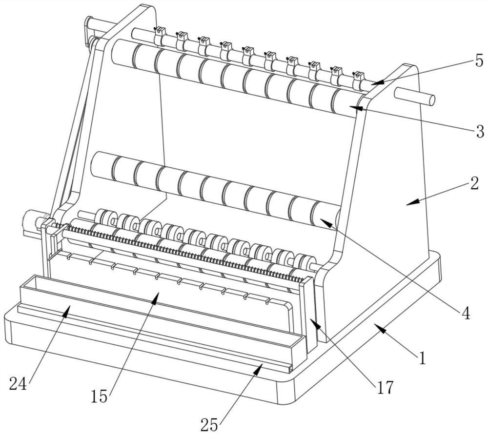
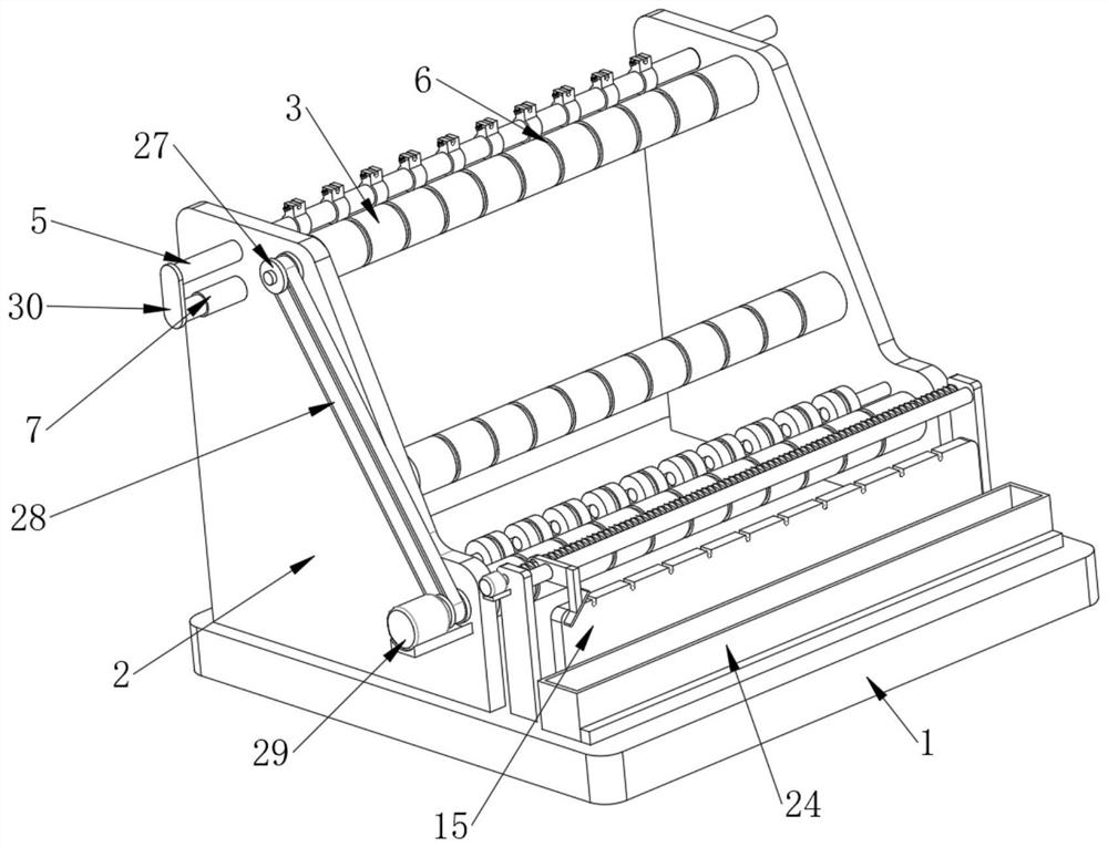
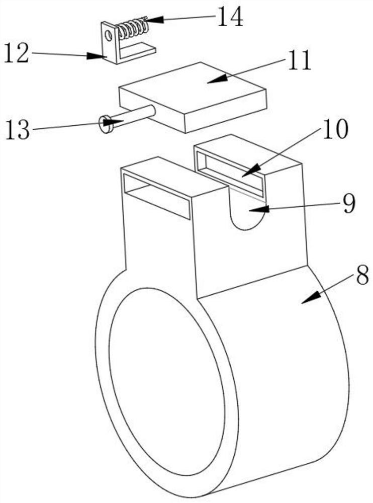

Image

  • Novel winder yarn guide device
  • Novel winder yarn guide device
  • Novel winder yarn guide device

Examples


Embodiment Construction

[0026] The following will clearly and completely describe the technical solutions in the embodiments of the present invention with reference to the accompanying drawings in the embodiments of the present invention. Obviously, the described embodiments are only some, not all, embodiments of the present invention.

[0027] In describing the present invention, it should be understood that the terms "upper", "lower", "front", "rear", "left", "right", "top", "bottom", "inner", " The orientation or positional relationship indicated by "outside", etc. is based on the orientation or positional relationship shown in the drawings, and is only for the convenience of describing the present invention and simplifying the description, rather than indicating or implying that the referred device or element must have a specific orientation, so as to Specific orientation configurations and operations, therefore, are not to be construed as limitations on the invention.

[0028] refer to Figure ...


PUM


Abstract

The invention relates to the technical field of textile equipment, and discloses a novel winder yarn guide device. The novel winder yarn guide device comprises a base and a front plate, wherein side plates are fixedly arranged on the two sides of the top of the base, the front sides of the two side plates are movably connected with a first guide cylinder and a second guide cylinder in a sleeving manner respectively, the upper portions of the rear sides of the two side plates are movably connected with a moving rod in a sleeving manner, first yarn grooves are separately formed in the outer side of the first guide cylinder and the outer side of the second guide cylinder, and an air cylinder is fixedly arranged on one side of one side plate. According to the novel winder yarn guide device, a clamping plate, a spring, a pull rod and a supporting frame are arranged at the top of a yarn guide base respectively, the clamping plate seals the top of a second yarn groove in a free state of the spring, so that yarns can be conveniently limited in an inner cavity of the second yarn groove, and the circumstance that the yarns run out of the inner cavity of the second yarn groove when the device runs, and the yarn winding effect is influenced is prevented; and meanwhile, the pull rod is pulled to drive the clamping plate to move, the top of the second yarn groove is opened, and the yarns can be conveniently placed in the inner cavity of the second yarn groove.

Description

technical field [0001] The invention relates to the technical field of textile equipment, in particular to a novel yarn guiding device of a winder. Background technique [0002] At present, in the textile process, the winder is one of the necessary equipment in the post-spinning and preparation process of the textile enterprise. The yarn guide device is generally installed on the creel of the winder, and the yarn is drawn out from the coil. The guide or fixed device is sent to the cone-shaped basket of the winder, and it is wound into a cone-shaped object to realize the process of changing the yarn and checking whether the yarn is broken. [0003] The existing yarn guiding device of the new winder uses the wire base to guide the yarn, and then winds it on the conical round basket. However, the existing wire base only has a wire opening to limit the position of the yarn. This makes it easy for the yarn to run out of the wire seat when it moves back and forth, which affects t...

Claims


Application Information

Patent Timeline
IPC IPC(8): B65H57/04B65H54/30B65H54/553B65H54/44B65H54/70B65H51/06
CPCB65H57/04B65H54/30B65H54/553B65H54/44B65H54/702B65H51/06B65H2701/31
Inventor 张文栋
Owner JINMING KNITTING
Learn More