
Vortex ring generating device, air conditioner indoor unit and air conditioner

A technology of generating device and vortex ring, which is used in air-conditioning systems, space heating and ventilation, space heating and ventilation details, etc. It can solve the problems of small force-bearing area and action area of ​​the film, easily affecting the sealing performance, and increasing costs.

Pending Publication Date: 2021-05-04
GD MIDEA AIR-CONDITIONING EQUIP CO LTD +1
View PDF0 Cites 1 Cited by
  • Summary
  • Abstract
  • Description
  • Claims
  • Application Information

AI Technical Summary

Problems solved by technology

The vortex ring air supply part of the vortex ring generator can be a piston structure, but the piston structure needs to achieve a good seal with the cavity wall, so that the driving force to push the piston to move is greater, and the reciprocating movement of the piston is likely to affect the sealing performance. In turn, the effect of compressing the volume of the cavity is not good.
The vortex ring air supply part can also add a push rod structure for the whole film, that is, the push rod stretches or shrinks the film to squeeze the air in the cavity to form a vortex ring and blow it out. However, this structure requires extremely high elasticity of the film material. , and the damage rate of the film material is high, which in turn increases the cost
At the same time, because the push rod pushes the film to deform, the force-bearing area and action area of ​​the film are small, which makes the effect of the volume in the compression chamber not good, which affects the formation of the vortex ring and the blowing speed of the vortex ring airflow

Method used


Image

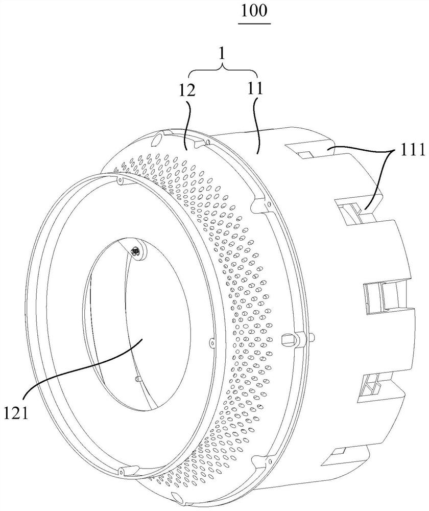
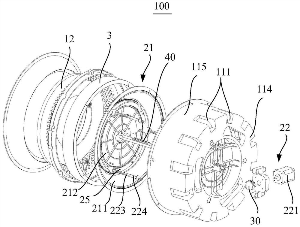
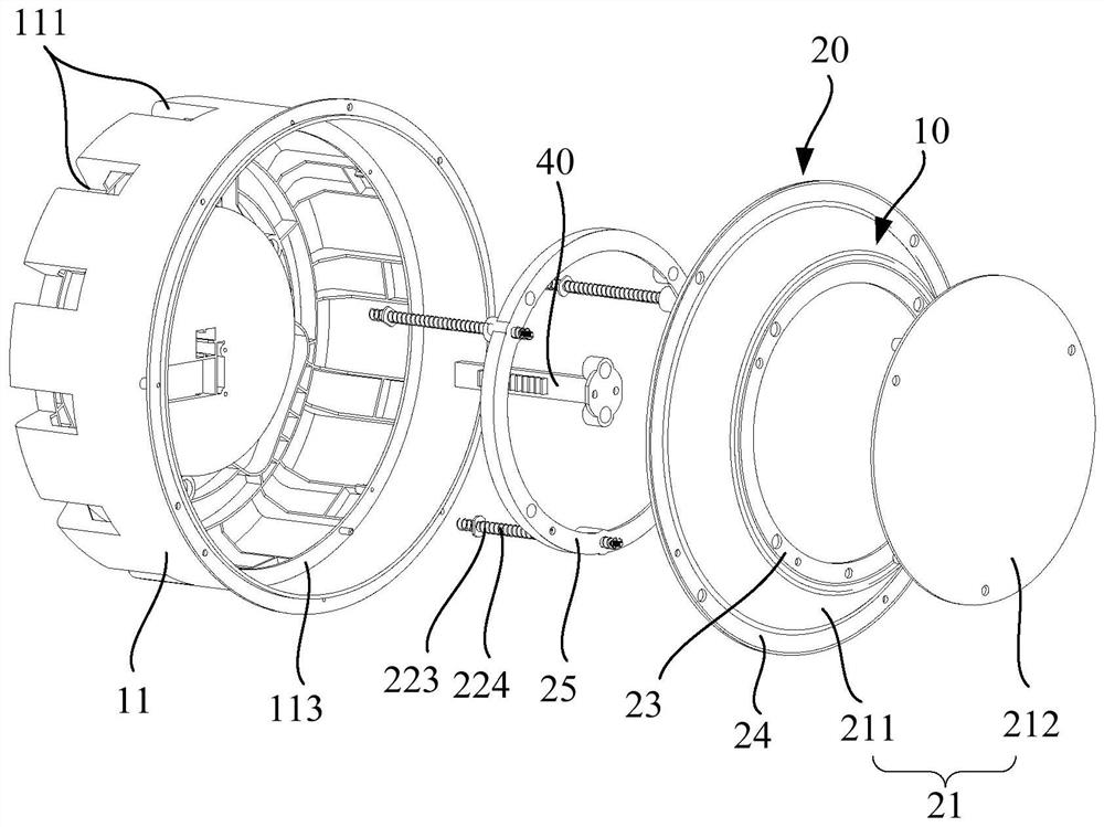
  • Vortex ring generating device, air conditioner indoor unit and air conditioner
  • Vortex ring generating device, air conditioner indoor unit and air conditioner
  • Vortex ring generating device, air conditioner indoor unit and air conditioner

Examples


Embodiment Construction

[0043] It should be noted that if there is a directional indication (such as up, down, left, right, front, back...) in the embodiment of the present invention, the directional indication is only used to explain the position in a certain posture (as shown in the accompanying drawing). If the specific posture changes, the directional indication will also change accordingly.

[0044]In addition, if there are descriptions involving "first", "second" and so on in the embodiments of the present invention, the descriptions of "first", "second" and so on are only for descriptive purposes, and should not be interpreted as indicating or implying Its relative importance or implicitly indicates the number of technical features indicated. Thus, the features defined as "first" and "second" may explicitly or implicitly include at least one of these features. In addition, the meaning of "and / or" appearing in the whole text includes three parallel schemes, taking "A and / or B" as an example, i...


PUM


Abstract

The invention discloses a vortex ring generating device, an air conditioner indoor unit and an air conditioner. The vortex ring generating device comprises a shell and a vortex ring generating portion; the shell comprises an air duct and a flow collecting piece, the air duct is provided with an air outlet, the flow collecting piece is installed at the air outlet, an air supply outlet communicating with the air duct is formed in the flow collecting piece, and an air passing area of the air supply outlet is smaller than that of the air outlet; and the vortex ring generating portion comprises a push plate assembly and a driving device, the push plate assembly is arranged in the shell and comprises a flexible part and a push plate connected to the flexible part, the flexible part is connected to the peripheral wall face of the shell, the push plate is arranged towards the air supply outlet, and the driving device drives the push plate to reciprocate in the shell so as to periodically drive airflow to be blown out of the air supply outlet. The vortex ring generating portion of the vortex ring generating device is simple in structure, high in sealing performance, high in reliability and low in cost.

Description

technical field [0001] The invention relates to the technical field of air conditioning, in particular to a vortex ring generator, an air conditioner indoor unit and an air conditioner. Background technique [0002] Existing air conditioners blow out the air after heat exchange through the conventional air outlet of the air conditioner. Range and long-distance air supply, reducing user experience. [0003] Long-distance air supply can be realized by setting the vortex ring generating device. The vortex ring air supply part of the vortex ring generator can be a piston structure, but the piston structure needs to achieve a good seal with the cavity wall, so that the driving force to push the piston to move is greater, and the reciprocating movement of the piston is likely to affect the sealing performance. And then make the effect of compressing the volume in the chamber bad. The vortex ring air supply part can also add a push rod structure for the whole film, that is, the ...

Claims


Application Information

Patent Timeline
IPC IPC(8): F24F1/0011F24F13/08F24F13/20
CPCF24F1/0011F24F13/081F24F13/20
Inventor 康铁生陈良锐张滔
Owner GD MIDEA AIR-CONDITIONING EQUIP CO LTD
Learn More