Multi-station marking machine

A marking machine and multi-station technology, applied in the field of marking machines, can solve problems such as large labor force, low efficiency, and unsafety

Inactive Publication Date: 2021-05-07
付会蓉
View PDF0 Cites 7 Cited by
  • Summary
  • Abstract
  • Description
  • Claims
  • Application Information

AI Technical Summary

Problems solved by technology

Such operations are labor intensive

Method used


Image

  • Multi-station marking machine
  • Multi-station marking machine
  • Multi-station marking machine

Examples


specific Embodiment approach 1

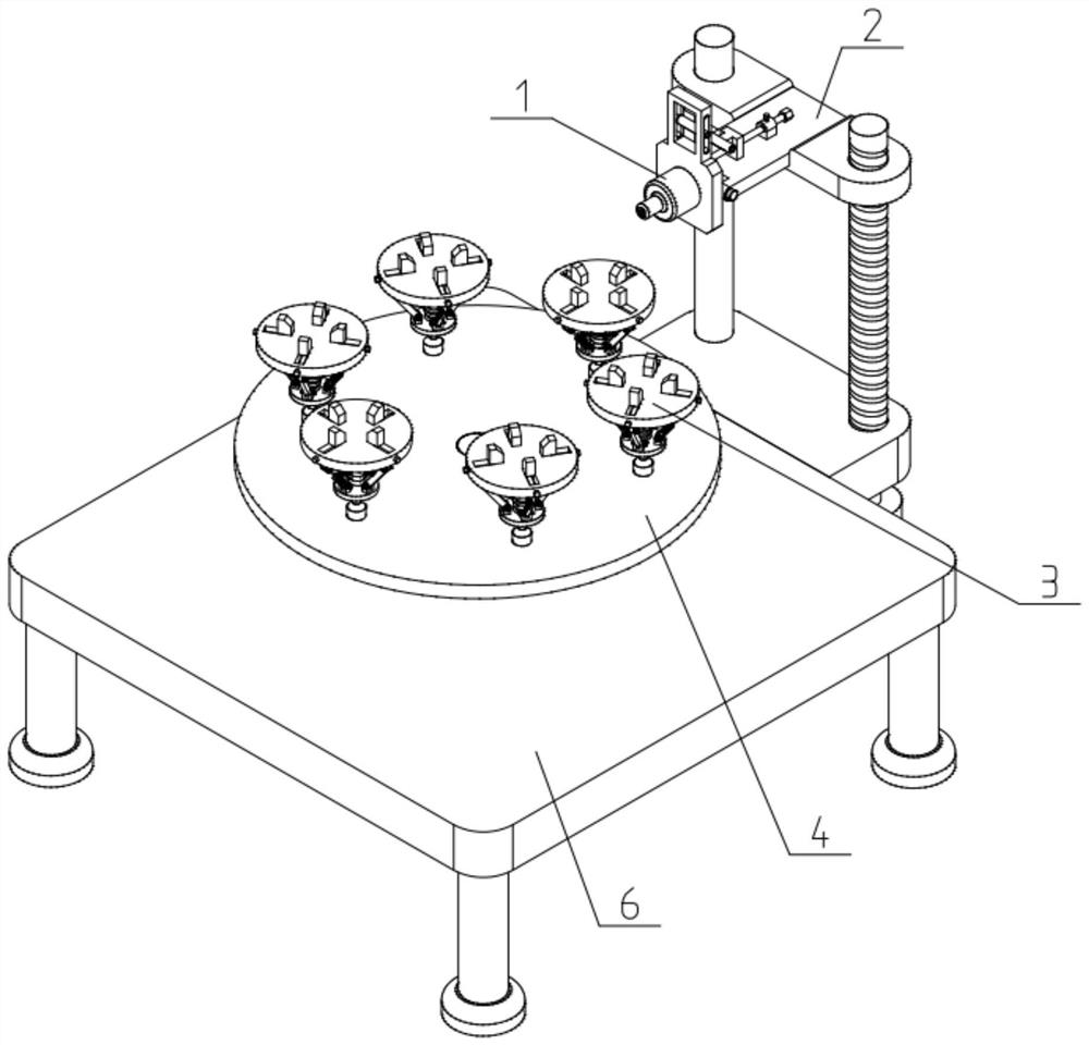
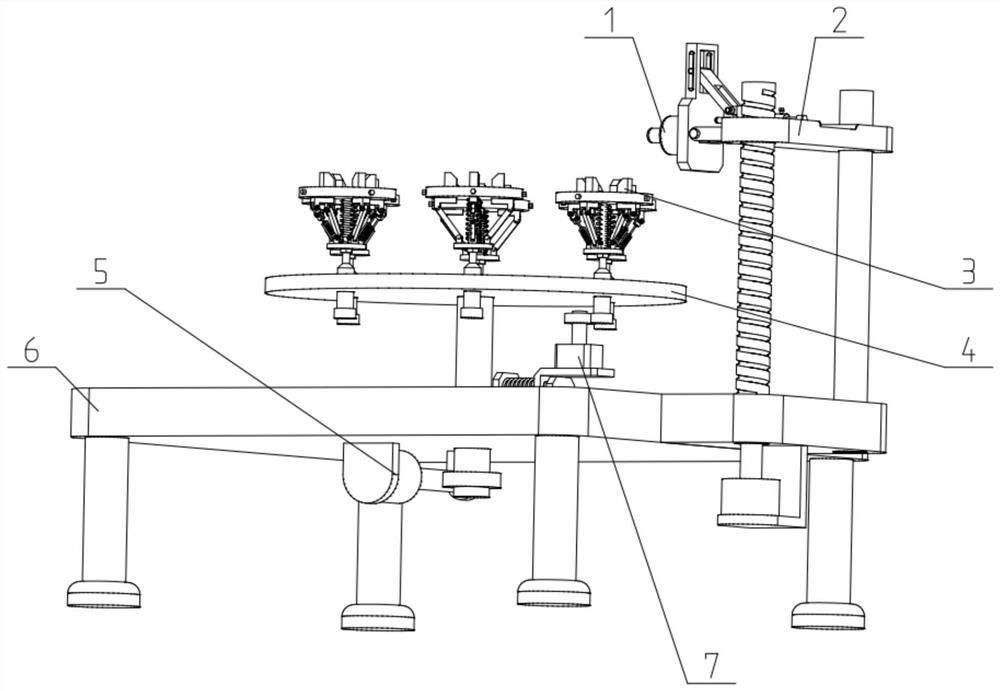
[0037] Such as Figure 1-11 As shown, a multi-station marking machine includes a laser marking machine 1, a marking machine mounting frame 2, a workpiece fixture 3, a rotating platform 4, a rotating drive mechanism 5 and a frame 6. The laser marking machine 1 fixed on the marking machine mounting frame 2; the marking machine mounting frame 2 is fixedly connected to the frame 6; the rotating drive mechanism 5 fixed on the frame 6 is connected to the rotating platform 4 , to drive the rotating platform 4 to rotate on the frame 6; the rotating platform 4 is uniformly surrounded and connected with a plurality of workpiece fixtures 3, so as to position the workpiece to be marked; the laser marking machine 1 cooperates It is arranged on the outside of the workpiece holder 3 . The present invention is equipped with a plurality of workpiece fixtures 3 inside, which can position a plurality of workpieces to be marked; inside is provided with a rotating platform 4 and a rotating drivin...

specific Embodiment approach 2

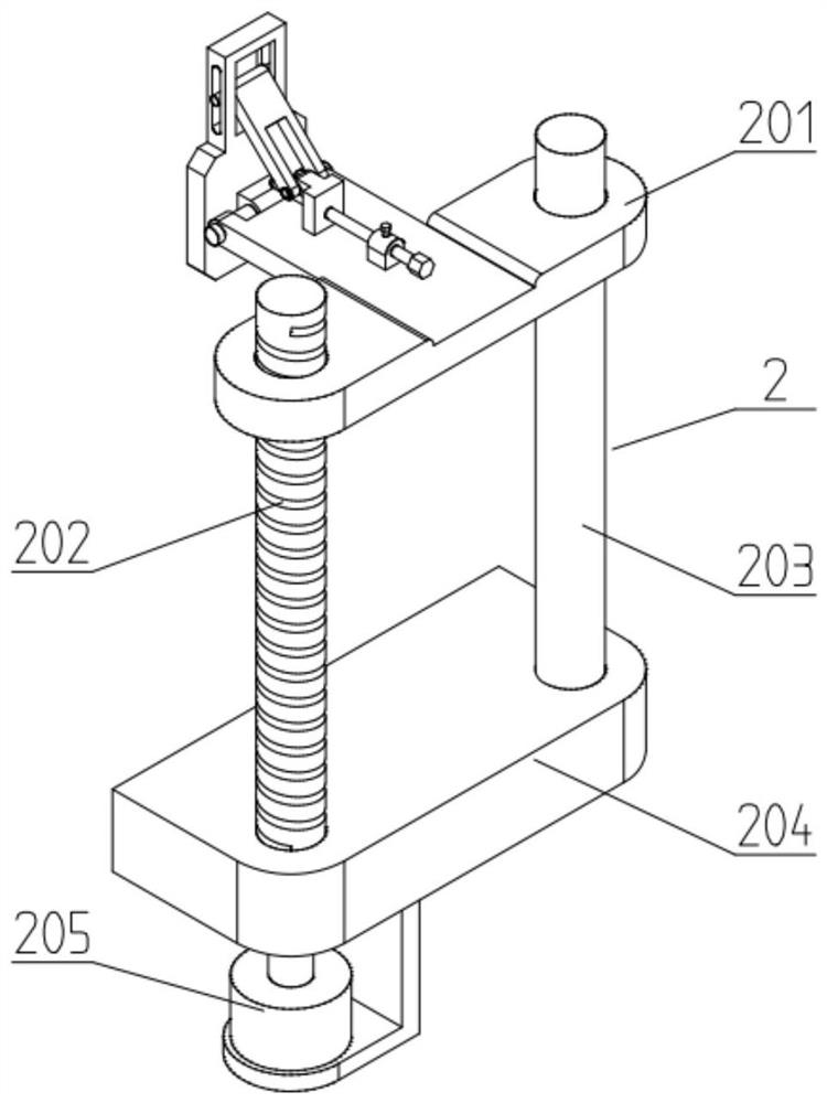
[0039] Such as Figure 1-11 As shown, the marking machine installation frame 2 includes an adjustable lifting frame 201, a screw 202, a vertical guide shaft 203, a horizontal seat 204 and a first servo motor 205; the horizontal seat 204 is fixed on the frame 6; A servo motor 205 is fixed on the cross seat 204 through a motor bracket; the output shaft of the first servo motor 205 is connected to the lead screw 202 through a coupling transmission; the lead screw 202 is rotated and fitted on the cross seat 204; The adjustable lifting frame 201 is connected to the bar 202 through screw transmission; the adjustable lifting frame 201 is slidably fitted on the guide vertical shaft 203; the guide vertical shaft 203 is fixed on the horizontal seat 204; the laser marking machine 1 Fixedly connected on the adjustable lifting frame 201. The height of the adjustable lifting frame 201 inside the marking machine installation frame 2 can be adjusted, thereby adjusting the horizontal position...

specific Embodiment approach 3

[0042] Such as Figure 1-11 As shown, the rotating platform 4 includes a platform body 401, a supporting shaft 402 and a worm wheel 403; the platform body 401 and the worm wheel 403 are respectively fixed on the upper and lower ends of the supporting shaft 402; the rotating drive mechanism 5 drives The worm gear 403 is connected; the platform body 401 is uniformly surrounded and fitted with a plurality of work clamps 3 . The quantity on the workpiece fixture 3 can be installed or disassembled according to actual needs.

[0043] The rotary drive mechanism 5 includes a second servo motor 501, a worm 502 and a rod holder 503; the second servo motor 501 is fixed on the frame 6 through a motor bracket; the output shaft of the second servo motor 501 One end of the worm 502 is connected through a coupling; the worm 502 is meshed and connected to the worm wheel 403;

[0044] After the second servo motor 501 is powered on, it can drive the worm 502 to rotate, and the worm 502 can dri...


PUM


Abstract

The invention relates to the technical field of marking machines, in particular to a multi-station marking machine. The multi-station marking machine comprises a laser marking machine, a marking machine mounting frame, a plurality of workpiece clamps, a rotating platform, a rotating driving mechanism and a rack, and the laser marking machine is fixed to the marking machine mounting frame. The marking machine mounting frame is fixedly connected to the rack. The rotating driving mechanism fixed to the rack is in transmission connection with the rotating platform so as to drive the rotating platform to rotate on the rack. The multiple workpiece clamps are uniformly connected to the rotating platform in a surrounding and matching manner so as to position workpieces to be marked. The laser marking machine is arranged on the outer sides of the workpiece clamps in a matched mode. The multiple workpiece clamps are arranged in the multi-station marking machine, the multiple workpieces can be clamped and positioned, the workpieces are sequentially conveyed to the position opposite to the laser marking machine to be marked, efficiency is high, and safety is high.

Description

technical field [0001] The present invention relates to the technical field of marking machines, more specifically, to a multi-station marking machine. Background technique [0002] At present, when the conventional marking machine is marking, the material is manually fed, and it is necessary to manually take the parts to be marked and put them in the fixing hole under the marking head, and hold them by hand, and then use the marking head to mark. mark. Such operations are labor intensive, inefficient, and relatively unsafe. Contents of the invention [0003] The purpose of the present invention is to provide a multi-station marking machine, which can effectively solve the problems in the prior art; the present invention is equipped with multiple workpiece clamps, which can clamp and position multiple workpieces, and send them to the The marking process is carried out at the position opposite to the laser marking machine, which has high efficiency and high safety. [00...

Claims


Application Information

Patent Timeline
IPC IPC(8): B23K26/362B23K26/08B23K26/70B23K37/04
CPCB23K26/0823B23K26/362B23K37/0443B23K26/702
Inventor 付会蓉
Owner 付会蓉
Why Eureka
Try Eureka