
A clamping device applicable to the machining of metal pipe fittings in machining centers

A technology for clamping devices and metal pipe fittings, applied in metal processing mechanical parts, positioning devices, metal processing equipment, etc., can solve the problems of affecting processing accuracy, poor clamping speed and accuracy, affecting processing speed, etc. Chip evacuation ability, ensure stability and accuracy, and reduce the effect of contact area

Active Publication Date: 2022-02-08
DONGGUAN JIR FINE MACHINERY
View PDF8 Cites 0 Cited by
  • Summary
  • Abstract
  • Description
  • Claims
  • Application Information

AI Technical Summary

Problems solved by technology

[0003] However, some fixtures used in conjunction with machining centers are used in the processing of some metal pipe fittings. Traditional machining center fixtures are difficult to achieve both in terms of clamping accuracy, speed and chip removal capabilities. Usually, the fixtures with stronger chip removal capabilities The clamping speed and precision are poor, which affects the processing rate, while the fast clamping speed and high precision leave less space for chip removal, and it is easy to cause metal chips to accumulate during processing, which affects heat dissipation and processing. Precision, with the rapid development of machinery, the requirements for parts precision and production efficiency are getting higher and higher, and the clamping devices commonly used in the past can no longer meet the processing requirements

Method used


Image

  • A clamping device applicable to the machining of metal pipe fittings in machining centers
  • A clamping device applicable to the machining of metal pipe fittings in machining centers
  • A clamping device applicable to the machining of metal pipe fittings in machining centers

Examples


Embodiment Construction

[0030] The following will clearly and completely describe the technical solutions in the embodiments of the present invention with reference to the accompanying drawings in the embodiments of the present invention. Obviously, the described embodiments are only some, not all, embodiments of the present invention. Based on the embodiments of the present invention, all other embodiments obtained by persons of ordinary skill in the art without making creative efforts belong to the protection scope of the present invention.

[0031] Unless otherwise defined, the technical terms or scientific terms used in the present disclosure shall have the usual meanings understood by those skilled in the art to which the present disclosure belongs. The words "comprising" or "comprising" and similar words used in the present disclosure mean that the elements or things appearing before the word include the elements or things listed after the word and their equivalents, without excluding other elem...


PUM


Abstract

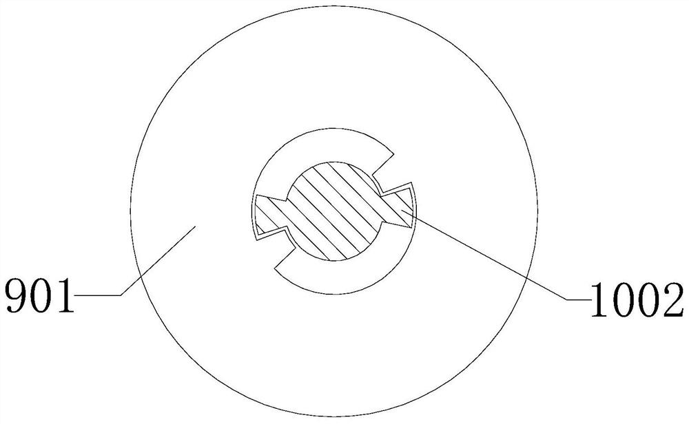
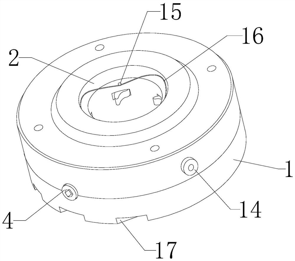
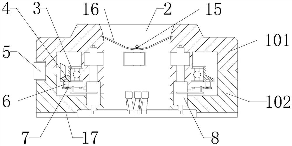
The invention provides a clamping device applicable to the processing of metal pipe fittings in a machining center, which includes a housing, the housing is composed of an upper housing and a lower housing, and a circular through-hole installation hole is arranged in the middle of the housing. The inner side of the upper housing is nested with a bearing, and the outer side of the bearing is fixed with a ring gear, which is connected to the fastening screw on one side of the housing by transmission. A number of fasteners hinged between the casing and the lower casing are connected by transmission. The fasteners are composed of a transmission shaft, an upper latch and a lower latch. The upper and lower ends of the transmission shaft are respectively movably connected with an upper latch and a lower latch. , the transmission shaft is connected to the drive disc in the housing, the fastener of the present invention can hold the bottom of the metal pipe for easy clamping, and clamp the metal pipe from two heights on the inner and outer sides and the axial direction of the metal pipe , while reducing the contact area and leaving a large space for chip removal, it also ensures the stability and accuracy of the clamping, and has a good development prospect.

Description

technical field [0001] The invention relates to the technical field of processing metal pipe fittings, in particular to a clamping device applicable to the processing of metal pipe fittings in a machining center. Background technique [0002] Machining center refers to the machining center where the axis of the spindle is set perpendicular to the workbench. It is mainly suitable for processing complex parts such as plates, discs, molds and small shells; the machining center can complete milling, boring, drilling, tapping and cutting Thread and other processes. After the workpiece is once clamped on the machining center, the digital control system can control the machine tool to automatically select and replace the tool according to different procedures, automatically change the machine tool spindle speed, feed rate, and the movement track of the tool relative to the workpiece and other auxiliary functions. Multi-process processing on several surfaces of the workpiece, and m...

Claims


Application Information

Patent Timeline
Patent Type & Authority Patents(China)
IPC IPC(8): B23Q3/06B23Q11/10B23Q11/00
CPCB23Q3/064B23Q11/10B23Q11/0042
Inventor 黄日恒王有亮李东梁区
Owner DONGGUAN JIR FINE MACHINERY
Learn More