Method and system for high-temperature detection of activated carbon and cooling and extinguishing of spontaneous combustion activated carbon

An activated carbon, high temperature technology, applied in chemical instruments and methods, inorganic chemistry, non-metallic elements, etc., can solve the problems of difficult detection and disposal of high temperature activated carbon particles

Active Publication Date: 2021-05-07
HUNAN ZHONGYE CHANGTIAN ENERGY CONSERVATION & ENVIRONMENTAL PROTECTION TECH CO LTD
View PDF6 Cites 0 Cited by
  • Summary
  • Abstract
  • Description
  • Claims
  • Application Information

AI Technical Summary

Problems solved by technology

The technical solution proposed by the invention detects spontaneously ignited high-temperature activated carbon in the vibration screening link of the activated carbon flue gas purification device, and can locate and

Method used


Image

  • Method and system for high-temperature detection of activated carbon and cooling and extinguishing of spontaneous combustion activated carbon
  • Method and system for high-temperature detection of activated carbon and cooling and extinguishing of spontaneous combustion activated carbon
  • Method and system for high-temperature detection of activated carbon and cooling and extinguishing of spontaneous combustion activated carbon

Examples


Embodiment 1

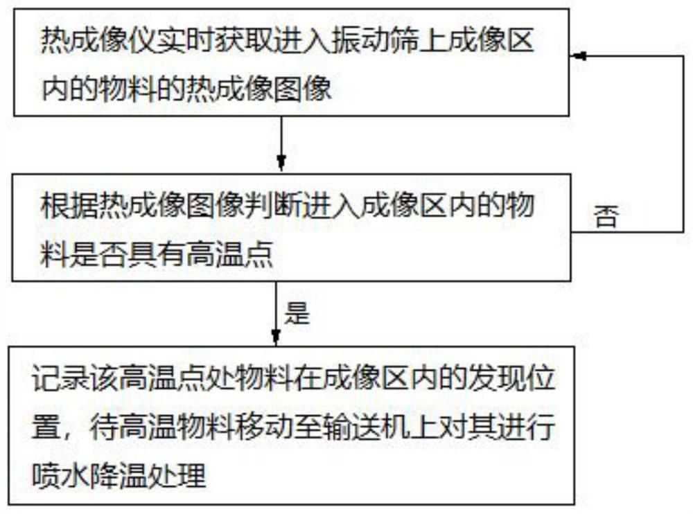
[0121] like Figure 9 As shown, a system for high-temperature detection of activated carbon and cooling and extinguishing of spontaneously ignited activated carbon, the system includes a thermal imager 1, a vibrating screen 2, a conveyor 5, and a cooling device for extinguishing spontaneously ignited activated carbon. The discharge port of the vibrating screen 2 is connected with the feed port of the conveyor 5 . The vibrating screen 2 is provided with a cover plate 201 . The thermal imager 1 is arranged above the cover plate 201 of the vibrating screen 2 . The conveyor includes a horizontal section and a vertical section, and the self-igniting activated carbon extinguishing cooling device is arranged above the horizontal section of the conveyor 5 . The vibrating screen 2 is provided with an imaging area 3 .

Embodiment 2

[0123] like Figure 12 and 13 As shown, embodiment 1 is repeated, except that the self-igniting activated carbon extinguishing cooling device is the cooling water spraying device 6 arranged above the horizontal section of the conveyor 5 . The conveyor 5 is a chain-bucket conveyor, and a plurality of chain buckets 501 are evenly arranged in the chain-bucket conveyor, and each chain bucket 501 opens upward. The cooling water spraying device 6 includes a cooling water main pipe 601 and a cooling water branch pipe 602 . Both the cooling water main pipe 601 and the cooling water branch pipe 602 are arranged directly above the horizontal section of the conveyor 5 . One end of the cooling water main pipe 601 is provided with a cooling water inlet, and the other end of the cooling water main pipe 601 is connected with a cooling water branch pipe 602 . The lower edge of the cooling water branch pipe 602 is provided with a spray hole 603 .

Embodiment 3

[0125]Embodiment 2 is repeated, except that the cooling water main pipe 601 is further provided with a cooling water valve 604 , and the cooling water valve 604 controls the opening and closing of the cooling water spraying device 6 . The cooling water branch pipe 602 is arranged parallel to the upper part of the chain bucket 501 and perpendicular to the length direction of the conveyor 5 . A plurality of spray holes 603 are opened on the cooling water branch pipe 602, and the plurality of spray holes 603 are evenly distributed. The length of the cooling water branch pipe 602 is equal to the width of the chain bucket 501 .


PUM


Abstract

A method for high-temperature detection of activated carbon and cooling and extinguishing of spontaneous combustion activated carbon comprises the following steps: 1) a thermal imager (1) shoots a material entering an imaging area (3) on a vibrating screen (2) in real time to obtain a thermal imaging image; 2) analyzing and judging whether the material entering the imaging area (3) has a high-temperature point or not according to the thermal imaging image; 2a) if it is judged that the thermal imaging image does not have the high-temperature point, repeating the step (1); 2b) if the thermal imaging image has the high-temperature point, recording the finding position of the material at the high-temperature point in the imaging area (3) on the vibrating screen (2); and 3) when the materials at the high-temperature points move to a conveyor (5), performing water spraying cooling treatment on the corresponding high-temperature materials. Spontaneous combustion high-temperature activated carbon is detected in the screening link of the activated carbon flue gas purification device and can be positioned and treated, the problem that high-temperature activated carbon particles are difficult to comprehensively detect and treat is solved, and the safety of the system is improved.

Description

technical field [0001] The invention relates to the detection and treatment of high-temperature activated carbon particles in an activated carbon flue gas purification device, in particular to a method and system for high-temperature detection of activated carbon and cooling and extinguishing of spontaneously combusted activated carbon, belonging to the technical field of activated carbon flue gas purification. Background technique [0002] The amount of flue gas produced in the sintering process accounts for about 70% of the entire iron and steel process, and the main pollutants in the sintering flue gas are dust, SO 2 , NO X ; In addition, there are a small amount of VOCs, dioxins, heavy metals, etc.; they need to be purified before they can be discharged. At present, the technology of activated carbon desulfurization and denitrification device for treating sintering flue gas has been mature, and it has been popularized and used in China, and good results have been achiev...

Claims


Application Information

Patent Timeline
IPC IPC(8): C01B32/39G01N25/20
CPCC01B32/39G01N25/20
Inventor 刘雁飞
Owner HUNAN ZHONGYE CHANGTIAN ENERGY CONSERVATION & ENVIRONMENTAL PROTECTION TECH CO LTD
Why Eureka
Try Eureka