Method and system for secondary detection and secondary treatment of high-temperature activated carbon

A technology of secondary detection and secondary treatment, which is used in the secondary detection and secondary treatment of high-temperature activated carbon, and the detection and treatment of high-temperature activated carbon particles. The effect of hidden danger, suitable temperature and easy detection and identification

Pending Publication Date: 2021-05-25
ZHONGYE-CHANGTIAN INT ENG CO LTD
View PDF0 Cites 0 Cited by
  • Summary
  • Abstract
  • Description
  • Claims
  • Application Information

AI Technical Summary

Problems solved by technology

like figure 1 As shown, the sintered activated carbon flue gas purification device circulates between the desorption tower and the adsorption tower. The desorption tower, adsorption tower, conveyor, vibrating screen, buffer bin and other links are all airtight structures. The existing sintered activated carbon flue gas purification device Failure to solve the problem of detecting, locating and processing localized small amounts of high-temperature activated carbon

Method used


Image

  • Method and system for secondary detection and secondary treatment of high-temperature activated carbon
  • Method and system for secondary detection and secondary treatment of high-temperature activated carbon
  • Method and system for secondary detection and secondary treatment of high-temperature activated carbon

Examples


Embodiment 1

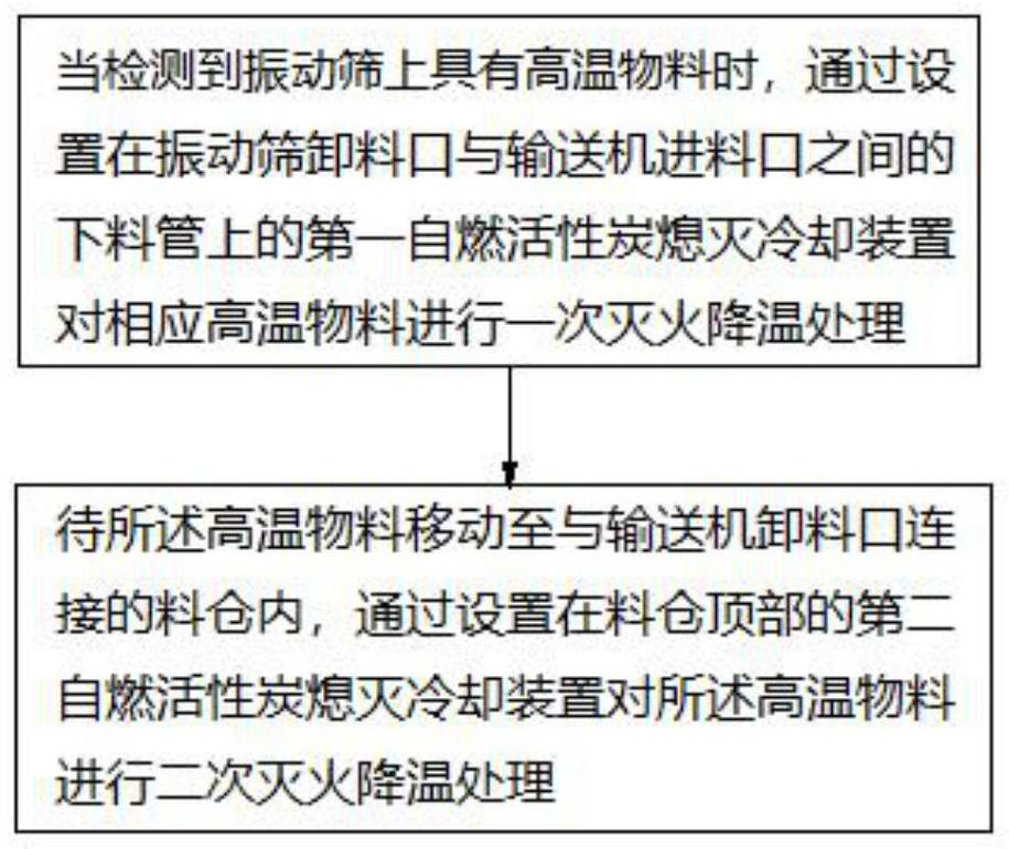
[0163] A system for secondary detection and secondary treatment of high-temperature activated carbon, the system includes a vibrating screen 1, a conveyor 2, a feeding pipe 3, a silo 4, a first self-ignition activated carbon extinguishing cooling device, and a second self-igniting activated carbon extinguishing cooling device. The discharge port of the vibrating screen 1 is connected with the feed port of the conveyor 2 through a discharge pipe 3 . The discharge port of the conveyor 2 is connected with the silo 4 . The first self-igniting activated carbon extinguishing cooling device is arranged on the feeding pipe 3 . The second self-igniting activated carbon extinguishing cooling device is arranged on the top of the feed bin 4 .

Embodiment 2

[0165] Such as Figure 13 and 14 As shown, Embodiment 1 is repeated, except that the system further includes a first thermal imager 5 and a first light shield 13 . The vibrating screen 1 is provided with a cover plate 101 . The first light shield 13 is arranged on the cover plate 101 at the rear of the vibrating screen 1 . The first thermal imager 5 is arranged on the top of the first light shield 13 . The rear part of the vibrating screen 1 is provided with an imaging I zone 6 . The imaging zone I 6 includes a first imaging zone 601 and a second imaging zone 602 , and the first imaging zone 601 is located upstream of the second imaging zone 602 . Taking the connection position of the first thermal imager 5 and the first shading cover 13 as a base point, the first thermal imager 5 swings back and forth around the base point. The first thermal imager 5 takes real-time pictures of the materials entering the first imaging area 601 and the second imaging area 602 at the tail ...

Embodiment 3

[0167] Such as Figure 15 and 16 As shown, embodiment 2 is repeated, except that the system further includes a second thermal imager 8 and a second hood 14 . A discharge hopper 7 is also provided between the conveyor 2 and the silo 4 . The discharge port of the conveyor 2 is connected with the inlet of the discharge hopper 7 through a discharge conduit 701 . The outlet of the unloading hopper 7 is connected with the inlet of the feed bin 4 through a feed pipe. The discharge conduit 701 is arranged on one side of the upper part of the discharge hopper 7 . The discharge conduit 701 includes an inclined section and a vertical section, and the vertical section is located downstream of the inclined section. The second shading cover 14 is arranged on the upper edge of the inclined section of the discharge conduit 701 . The second thermal imager 8 is arranged on the top of the second light shield 14 . An imaging II zone 9 is provided in the inclined section of the discharge con...


PUM


Abstract

The invention discloses a method for secondary detection and secondary treatment of high-temperature activated carbon, which comprises the steps of 1) when a material entering a vibrating screen (1) from a discharge port of a desorption tower is detected to have a high-temperature point, carrying out primary fire extinguishing and cooling treatment on thehigh-temperature material through a first spontaneous combustion activated carbon extinguishing and cooling device arranged on a discharging pipe (3) between the vibrating screen (1) and the conveyor (2); and (2) when the material at the high-temperature point moves into a stock bin (4) connected with a discharge port of the conveyor (2), carrying out secondary fire extinguishing and cooling treatment on the high-temperature material through a second spontaneous combustion activated carbon extinguishing and cooling device arranged at the top of the stock bin (4). The high-temperature activated carbon at the tail of the vibrating screen can be treated in time through primary treatment of the discharging pipe, and the high-temperature activated carbon can be further extinguished and cooled through secondary treatment of the stock bin, so that the extinguishment and cooling effects of the high-temperature material are ensured, and the safety of the system is improved.

Description

technical field [0001] The invention relates to the detection and treatment of high-temperature activated carbon particles in an activated carbon flue gas purification device, in particular to a method and system for secondary detection and secondary treatment of high-temperature activated carbon, and belongs to the technical field of activated carbon flue gas purification. Background technique [0002] The amount of flue gas produced in the sintering process accounts for about 70% of the entire iron and steel process, and the main pollutants in the sintering flue gas are dust, SO 2 , NO X ; In addition, there are a small amount of VOCs, dioxins, heavy metals, etc.; they need to be purified before they can be discharged. At present, the technology of activated carbon desulfurization and denitrification device for treating sintering flue gas has been mature, and it has been popularized and used in China, and good results have been achieved. [0003] The working schematic di...

Claims


Application Information

Patent Timeline
Patent Type & Authority Applications(China)
IPC IPC(8): G01J5/00
CPCG01J5/0066G01J2005/0077
Inventor 陈思墨周浩宇刘雁飞李谦王业峰刘前
Owner ZHONGYE-CHANGTIAN INT ENG CO LTD
Why Eureka
Try Eureka