Method and system for conducting secondary fire extinguishing and cooling treatment on high-temperature activated carbon

An activated carbon, high temperature technology, applied in separation methods, fire rescue, combustible gas purification/reconstruction, etc., can solve the problems of high temperature activated carbon detection, positioning and processing, achieve rapid extinguishing and cooling, avoid missed detection, improve safety effect

Active Publication Date: 2021-06-01
ZHONGYE-CHANGTIAN INT ENG CO LTD
View PDF6 Cites 0 Cited by
  • Summary
  • Abstract
  • Description
  • Claims
  • Application Information

AI Technical Summary

Problems solved by technology

like figure 1 As shown, the sintered activated carbon flue gas purification device circulates between the desorption tower and the adsorption tower. The desorption tower, adsorption tower, conveyor, vibrating screen, buffer bin and other links are all airtight structures. The existing sintered activated carbon flue gas purification device Failure to solve the problem of detecting, locating and processing localized small amounts of high-temperature activated carbon

Method used


Image

  • Method and system for conducting secondary fire extinguishing and cooling treatment on high-temperature activated carbon
  • Method and system for conducting secondary fire extinguishing and cooling treatment on high-temperature activated carbon
  • Method and system for conducting secondary fire extinguishing and cooling treatment on high-temperature activated carbon

Examples


Embodiment 1

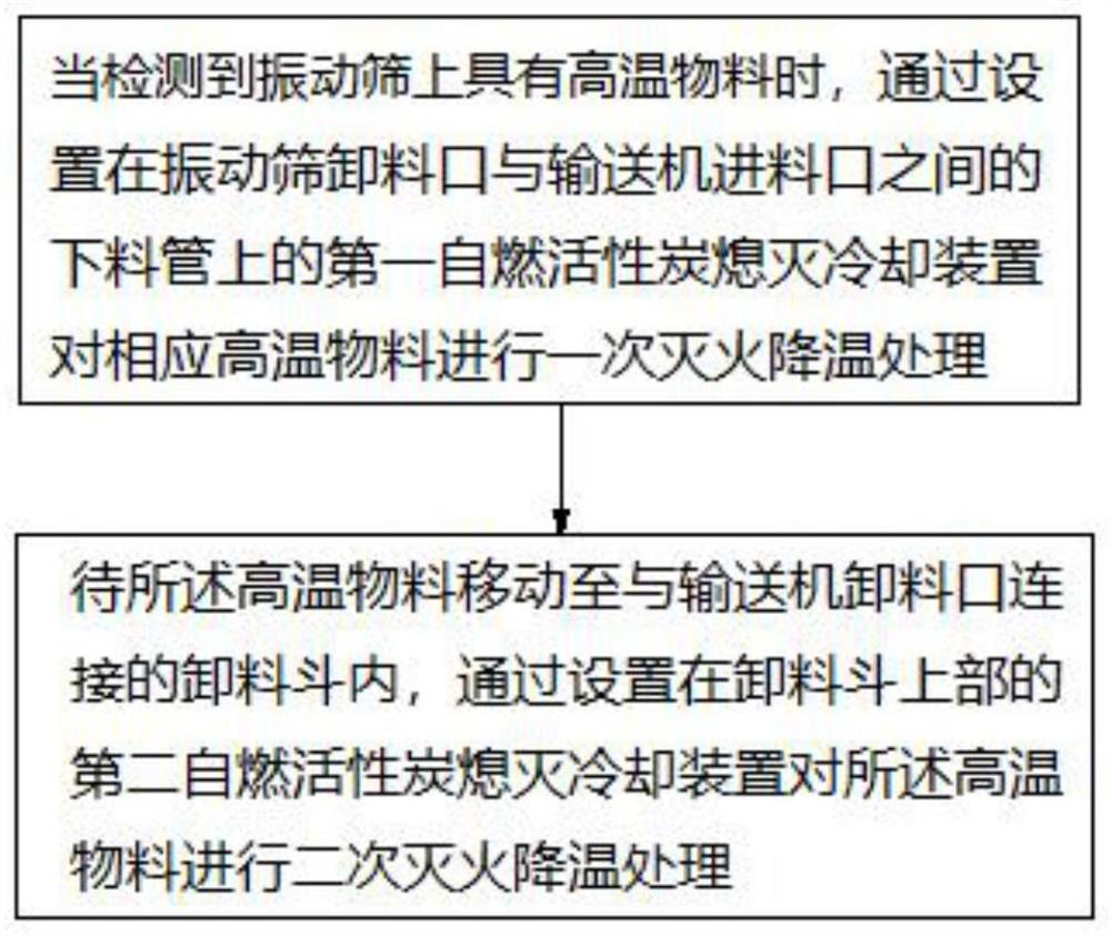
[0137] A system for secondary fire extinguishing and cooling treatment of high-temperature activated carbon, the system includes a vibrating screen 1, a conveyor 2, a feeding pipe 3, a discharge hopper 4, a first spontaneously ignited activated carbon extinguishing cooling device, and a second spontaneously igniting activated carbon extinguishing cooling device. The discharge port of the vibrating screen 1 is connected with the feed port of the conveyor 2 through a discharge pipe 3 . The discharge port of the conveyor 2 is connected with the discharge hopper 4 . The first self-igniting activated carbon extinguishing cooling device is arranged on the feeding pipe 3 . The second self-igniting activated carbon extinguishing cooling device is arranged on the top of the discharge hopper 4 .

Embodiment 2

[0139] Such as Figure 11 and 12 As shown, embodiment 1 is repeated, except that the system further includes a thermal imager 5 and a hood 10 . The vibrating screen 1 is provided with a cover plate 101 . The shading cover 10 is arranged on the cover plate 101 at the rear of the vibrating screen 1 . The thermal imaging camera 5 is arranged on the top of the light shield 10 . An imaging area 6 is provided at the end of the vibrating screen 1 . The imaging area 6 includes a first imaging area 601 and a second imaging area 602 , the first imaging area 601 is located upstream of the second imaging area 602 . Taking the connection position of the thermal imager 5 and the hood 10 as a base point, the thermal imager 5 swings back and forth around the base point. The thermal imager 5 takes real-time pictures of the materials entering the first imaging area 601 and the second imaging area 602 at the tail of the vibrating screen 1, and obtains a primary thermal imaging image and a s...

Embodiment 3

[0141] Embodiment 2 is repeated, except that the cover plate 101 at the rear of the vibrating screen 1 is provided with openings. The light shield 10 is located on the upper part of the opening. The width of the opening is equal to the width of the vibrating screen 1 .


PUM

PropertyMeasurementUnit
diameteraaaaaaaaaa
heightaaaaaaaaaa

Abstract

The invention provides a method for conducting secondary fire extinguishing and cooling treatment on high-temperature activated carbon. The method comprises the steps that firstly, when it is detected that materials entering a vibrating screen (1) have high-temperature points, primary fire extinguishing and cooling treatment is conducted on the high-temperature materials through a first spontaneous combustion activated carbon extinguishing and cooling device arranged on a discharging pipe (3) between the vibrating screen (1) and a conveyor (2); and secondly, when the materials at the high-temperature point move into a discharge hopper (4) connected with a discharge port of the conveyor (2), secondary fire extinguishing and cooling treatment is conducted on the high-temperature materials through a second spontaneous combustion activated carbon extinguishing and cooling device arranged at the upper part of the discharge hopper (4). High-temperature activated carbon at the tail of the vibrating screen can be treated in time through primary treatment of the discharging pipe, the high-temperature activated carbon can be further extinguished and cooled through secondary treatment of the discharging hopper, and therefore the extinguishment and cooling effects of high-temperature materials are ensured, and the safety of the system is improved.

Description

technical field [0001] The invention relates to the detection and treatment of high-temperature activated carbon particles in an activated carbon flue gas purification device, in particular to a method and system for secondary fire-extinguishing and cooling treatment of high-temperature activated carbon, and belongs to the technical field of activated carbon flue gas purification. Background technique [0002] The amount of flue gas produced in the sintering process accounts for about 70% of the entire iron and steel process, and the main pollutants in the sintering flue gas are dust, SO 2 , NO X ; In addition, there are a small amount of VOCs, dioxins, heavy metals, etc.; they need to be purified before they can be discharged. At present, the technology of activated carbon desulfurization and denitrification device for treating sintering flue gas has been mature, and it has been popularized and used in China, and good results have been achieved. [0003] The working schem...

Claims


Application Information

Patent Timeline
Patent Type & Authority Applications(China)
IPC IPC(8): A62C31/00A62C37/40B01J20/34
CPCA62C31/005A62C37/40B01J20/3416B01J20/3483Y02A50/20
Inventor 陈思墨周浩宇刘雁飞李谦王业峰刘前
Owner ZHONGYE-CHANGTIAN INT ENG CO LTD
Why Eureka
Try Eureka