High-temperature detection method and high-temperature detection system for activated carbon flue gas purification device

A flue gas purification and detection method technology, applied in the direction of radiation pyrometry, chemical instruments and methods, separation methods, etc., can solve the problems of inaccurate and incomplete detection of high-temperature activated carbon particles, so as to eliminate observation obstacles and improve safety performance, and the effect of improving accuracy

Active Publication Date: 2021-05-28
HUNAN ZHONGYE CHANGTIAN ENERGY CONSERVATION & ENVIRONMENTAL PROTECTION TECH CO LTD
View PDF7 Cites 0 Cited by
  • Summary
  • Abstract
  • Description
  • Claims
  • Application Information

AI Technical Summary

Problems solved by technology

The present invention adopts the high-temperature detection method of a thermal imager, through preliminary judgment of suspected high-temperature points, and tracking and determination of suspected high-temperature points, thereby obtaining accurate judgment data of high-temperature points, and solving the problem of high-temperature activated carbon particle detection in an activated carbon flue gas purification device. Accurate and incomplete detection of problems, improving system security

Method used


Image

  • High-temperature detection method and high-temperature detection system for activated carbon flue gas purification device
  • High-temperature detection method and high-temperature detection system for activated carbon flue gas purification device
  • High-temperature detection method and high-temperature detection system for activated carbon flue gas purification device

Examples


Embodiment approach

[0088]According to a second embodiment of the present invention, a high temperature detection system for activated carbon flue gas purification means is provided.

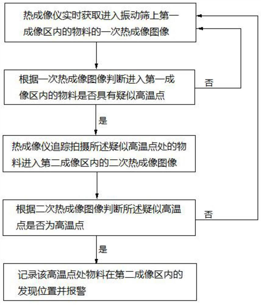
[0089]An active carbon smotting device high temperature detection system or a high temperature detection system for the active carbon flue gas purification apparatus for the method of the first embodiment, the system including thermal imaging instrument 1, vibrating screen 2, and observation device 4. A cover sheet 201 is provided on the vibrating screen 2. The thermal imager 1 is disposed above the vibrating screen 2 cover. The observation apparatus 4 is disposed at the upper portion of the vibrating screen 2 cover 201, and is located between the vibrating screen 2 cover 201 and the thermal imaging device 1. The vibrating screen 2 is provided with a first imaging region 301 and a second imaging region 302, and the first imaging region 301 is located upstream of the second imaging region 302. The thermal imaging device 1 su...

Embodiment 1

[0098]Such asFigure 4 with5As shown, a high temperature detection system of activated carbon flue gas purification means includes a thermal imaging device 1, a vibrating screen 2, and a viewing device 4. A cover sheet 201 is provided on the vibrating screen 2. The thermal imager 1 is disposed above the vibrating screen 2 cover. The observation apparatus 4 is disposed at the upper portion of the vibrating screen 2 cover 201, and is located between the vibrating screen 2 cover 201 and the thermal imaging device 1. The vibrating screen 2 is provided with a first imaging region 301 and a second imaging region 302, and the first imaging region 301 is located upstream of the second imaging region 302. The thermal imaging device 1 is performed on the vertical plane in a vertical plane around the viewing device 4, and the thermal imager 1 is performed by the observation device 4 on the first imaging region 301 and the second imaging region 302 in the vibrating screen 2. Real-time shooting, ...

Embodiment 2

[0100]Such asFigure 6 As shown, the Example 1 is repeated, except that the observation device 4 is observed in the thermal imaging. The thermal imager observer includes a side wall cover body 401, a top viewing hole 402, and a bottom viewing aperture 403. Wherein, the area formed by the top edge edge of the side wall cover 401 is the top viewing hole 402. The area enclosed by the bottom end edge of the side wall cover 401 is the bottom viewing hole 403. The thermal imaging device 1 performs real-time shooting of the first imaging region 301 and the bottom viewing region 301 and the bottom viewing hole 403, and then acquires a thermal imaging image and a secondary thermal imaging. image.


PUM

PropertyMeasurementUnit
diameteraaaaaaaaaa
heightaaaaaaaaaa

Abstract

The invention discloses a high-temperature detection method and high-temperature detection system for an activated carbon flue gas purification device. The high-temperature detection method for an activated carbon flue gas purification device comprises the following steps: 1), a thermal imager (1) shoots a material entering a first imaging area (301) on a vibrating screen (2) in real time to obtain a primary thermal imaging image; and 2), analysis is performed according to the primary thermal imaging image and whether the material entering the first imaging area (301) has a high-temperature point or not is determined; if so, the thermal imager (1) tracks and shoots a secondary thermal imaging image, entering a second imaging area (302) on the vibrating screen (2), of the material at a suspected high-temperature point, and whether the suspected high-temperature point is a high-temperature point or not is judged; and if the suspected high-temperature point is determined to be a high-temperature point, recording the finding position of the material at the high-temperature point in a second imaging area (302) on the vibrating screen (2) is recorded, and an alarm is made. The high-temperature activated carbon particles are detected by adopting the high-temperature activated carbon particle detection device, the detection accuracy can be improved, meanwhile, the problem that comprehensive detection is difficult is solved, and the safety of a system is improved.

Description

Technical field[0001]The present invention relates to the detection of high temperature activated carbon particles in the active carbon flue gas purifying apparatus, and specifically, a high temperature detection method of activated carbon flue gas purification means and its detection system belongs to the field of activated carbon smotting.Background technique[0002]The amount of flue gas generated by the sintering process accounts for about 70% in the steel full process, and the main pollutant components in the sintered flue gas are dust, so2NOXThere is also a small amount of VOCS, two dioxin, heavy metals, etc .; after purification is required. At present, the technology of activated carbon dethyldulfur debride debris deinterletter is mature, and it has been promoted in China, and has achieved good results.[0003]The prior art method of working in the active carbon deinterlean deinterletter is likefigure 1 As shown: the original flue gas generated by the sintering process (the main...

Claims


Application Information

Patent Timeline
Patent Type & Authority Applications(China)
IPC IPC(8): G01J5/00B01D53/02
CPCG01J5/0066B01D53/02G01J2005/0077B01D2259/40088Y02A50/20
Inventor 刘雁飞刘昌齐李勇
Owner HUNAN ZHONGYE CHANGTIAN ENERGY CONSERVATION & ENVIRONMENTAL PROTECTION TECH CO LTD
Why Eureka
Try Eureka