A Combinable Foundation Pit Support System
A technology for foundation pit support and foundation pit, which is applied in basic structure engineering, construction, excavation, etc., can solve the problems of high demolition construction intensity, achieve high disassembly and assembly efficiency, avoid left and right shaking, and demolition difficulty and labor-saving effects.
- Summary
- Abstract
- Description
- Claims
- Application Information
AI Technical Summary
Problems solved by technology
Method used
Image

Examples
Embodiment 1
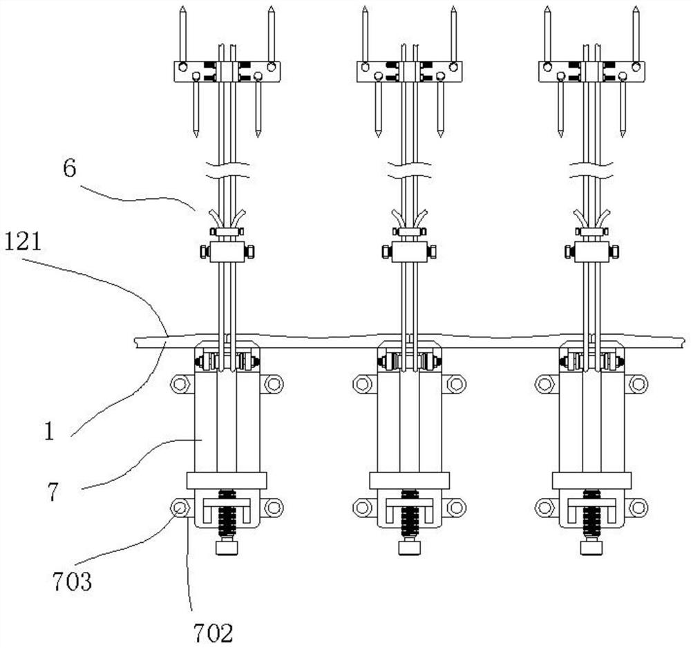
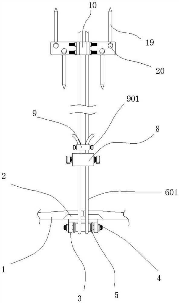
[0042] A combinable foundation pit support system, comprising a support plate 1, the support plate 1 is provided with a plurality of pieces, and a pressure plate 2 is installed between two adjacent support plates 1; the pressure plate 2 is far away from A swivel seat 3 is welded at the top position of the end face of the support plate 1, and a stud bolt 4 is fitted through the swivel seat 3, and a sleeve 5 is mounted on the stud bolt 4, and the sleeve 5 The cylinder 5 can rotate along the stud bolt 4; the sleeve 5 is fitted with a suspension structure 6, and the end of the suspension structure 6 away from the sleeve 5 is fixed on the ground, and the support The lower end surfaces of the plate 1 and the pressing plate 2 are all against the inner bottom surface of the foundation pit; a push plate 7 is arranged on the outside of the pressing plate 2, and the pushing plate 7 acts on the inner bottom of the foundation pit, and the pushing plate 7 The rear end of the rear end is pro...
Embodiment 2
[0044] Both ends of the support plate 1 are provided with wedge grooves 101, the pressure plate 2 fits between the two support plates 1, and the pressure plate 2 has a wedge 201 snapped into the wedge groove 101 The above-mentioned structure can make the cooperation between the pressure plate 2 and the support plate 1 more stable, and avoid the lateral swing of the pressure plate 2.
Embodiment 3
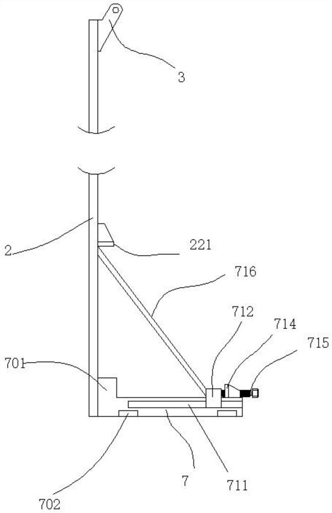
[0046] The left and right sides of the push plate 7 are all provided with chute 711, and the top of the push plate 7 is provided with a moving block 712, and the inner two sides of the moving block 712 are provided with fittings for matching the chute 711. Slider 713; a vertical plate 714 is provided near the front end of the top of the push plate 7, and a force screw 715 is matched with the vertical plate 714, and the force screw 715 is screwed in and resists the moving block 712 ; The moving block 712 is equipped with a diagonal strut 716, and a retaining bar 221 is welded at the front end of the pressing plate 2, and the diagonal strut 716 is limited at the bottom of the retaining bar 221; when the pressing plate 2 When the vertical height is high, the support in the middle is relatively weak and prone to bending. Therefore, we have designed the above structure. A pressure can be formed on the surface of the pressure plate 2 through the diagonal brace 716, so that the surfac...
PUM
 Abstract
Description
Claims
Application Information
 - R&D
- Intellectual Property
- Life Sciences
- Materials
- Tech Scout
- Unparalleled Data Quality
- Higher Quality Content
- 60% Fewer Hallucinations
Browse by: Latest US Patents, China's latest patents, Technical Efficacy Thesaurus, Application Domain, Technology Topic, Popular Technical Reports.
© 2025 PatSnap. All rights reserved.Legal|Privacy policy|Modern Slavery Act Transparency Statement|Sitemap|About US| Contact US: help@patsnap.com