Gasoline engine particle trap fuel economizer and regeneration control strategy

A particle filter and regeneration control technology, which is applied to the electronic control of exhaust treatment devices, exhaust devices, mufflers, etc., can solve the problem of reducing the passive regeneration opportunities of particle filters, fuel economy, driving performance, Unfavorable particle filter carbon cleaning and other issues

Active Publication Date: 2021-05-07
UNITED AUTOMOTIVE ELECTRONICS SYST
View PDF8 Cites 2 Cited by
  • Summary
  • Abstract
  • Description
  • Claims
  • Application Information

AI Technical Summary

Problems solved by technology

This solution will cause a decrease in vehicle fuel economy, and the prohibition of engine oil cut-off will reduce the chance of passive regeneration of the particulate filter, which is not conducive to the carbon removal of the particulate filter
Using the method of prohibiting fuel cut-off to avoid burning of the particulate filter will have a significant impact on fuel economy and drivability, so it is necessary to find a method other than "prohibit fuel cut-off" to solve this engineering problem

Method used


Image

  • Gasoline engine particle trap fuel economizer and regeneration control strategy
  • Gasoline engine particle trap fuel economizer and regeneration control strategy
  • Gasoline engine particle trap fuel economizer and regeneration control strategy

Examples


Embodiment 1

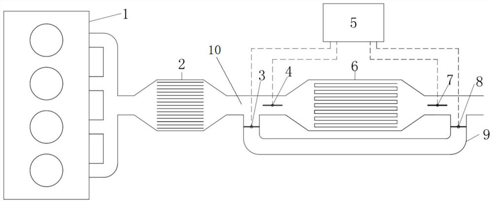
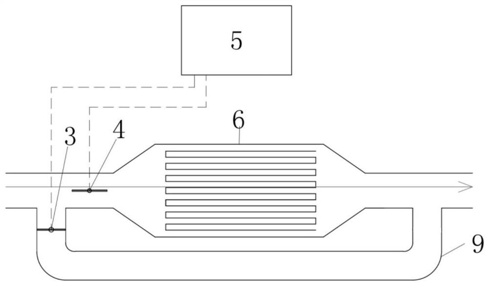
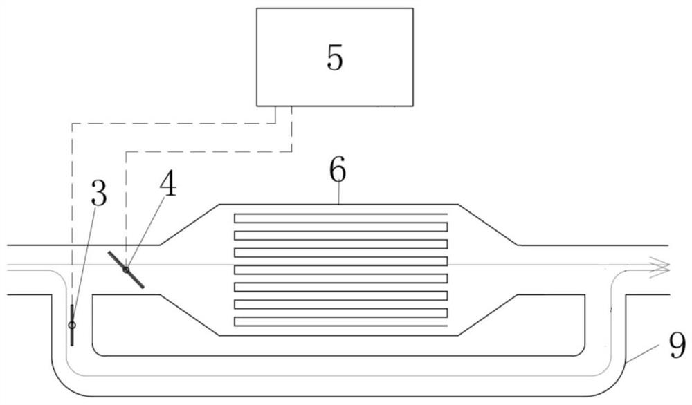
[0031] Embodiment 1. In this example, there are two solenoid valves, including solenoid valve one 3 and solenoid valve two 4, which saves the setting of solenoid valves and reduces the cost of the fuel-saving device for the gasoline engine particle filter. Solenoid valve one 3 is arranged at one end of bypass pipeline 9 , and solenoid valve two 4 is arranged on the main pipeline 10 at the front end of particle trap 6 . The controller is an electronic controller 5 .

[0032] The electronic controller 5 judges according to the central model temperature and model carbon amount of the particle trap in the controller algorithm, such as judging that there is no risk of burning the particle trap when the engine is cut off, and the accumulated carbon amount of the particle trap 6 is a safe carbon amount , it enters into the working mode of safe carbon quantity without oil cut-off.

[0033] The judgment of the model temperature and model carbon content of the particulate filter is bas...

Embodiment 2

[0044] Embodiment 2. In this example, there are four solenoid valves, including solenoid valve one 3, solenoid valve two 4, solenoid valve three 7 and solenoid valve four 8. Solenoid valve one 3 and solenoid valve four 8 are respectively arranged in the bypass At both ends of the pipeline 9 , the solenoid valve 2 4 and the solenoid valve 3 7 are respectively arranged on the main pipeline 10 at the front end and the rear end of the particle trap 6 . The controller is an electronic controller 5 . Two solenoid valves are respectively arranged on the bypass pipeline 9 and the main pipeline 10, which can ensure the stability of the control.

[0045] The electronic controller 5 judges according to the central model temperature and model carbon amount of the particle trap in the controller algorithm, such as judging that there is no risk of burning the particle trap when the engine is cut off, and the accumulated carbon amount of the particle trap 6 is a safe carbon amount , it ente...


PUM


Abstract

The invention relates to the technical field of gasoline engine particle traps, in particular to a gasoline engine particle trap fuel economizer and a regeneration control strategy. The gasoline engine particle trap fuel economizer comprises a particle trap, a controller, valves and an auxiliary pipeline. Main pipelines are arranged at the front end and the rear end of the particle trap, and the main pipeline at the front end of the particle trap is connected with one end of a bypass pipeline. The main pipeline at the rear end of the particle trap is connected with the other end of the bypass pipeline, the bypass pipeline and the main pipeline are each provided with one or more valves, and the controller controls the opening degree of the valves. Compared with the prior art, the bypass pipeline and the valves are additionally arranged at the front end and the rear end of the particle trap, the opening degree of the valves is controlled through the controller, normal fuel cut-off can be achieved under any carbon content of the particle trap, and the fuel economy and drivability of a whole vehicle are improved. The burning risk of the particle trap under the working condition of fuel cut-off of the engine can be effectively avoided. The opening degree of the valves can control the air flow entering the particle trap, and then carbon cleaning of the particle trap is safely and stably achieved.

Description

technical field [0001] The invention relates to the technical field of gasoline engine particulate traps, in particular to a fuel-saving device and regeneration control strategy for gasoline engine particulate traps. Background technique [0002] During engine operation, particulate emissions are produced. As emission regulations become increasingly stringent, more and more automobile manufacturers reduce particulate emissions by installing gasoline engine particulate filters. As the particulate matter continues to accumulate in the particulate filter, when the engine is cut off, the air enters the particulate filter along with the exhaust system, and the particulate matter in the particulate filter will burn and heat up. If the temperature increase at this time is too high, there is a risk of burning the particulate filter carrier. [0003] For the above risks, the current mainstream solution is: when the particulate matter accumulated in the particulate filter is large a...

Claims


Application Information

Patent Timeline
Patent Type & Authority Applications(China)
IPC IPC(8): F01N3/025F01N11/00F01N13/00
CPCF01N3/025F01N11/00F01N13/00Y02T10/40
Inventor 张鹏超李显明张虹姚辉王永飞孔德立曹政黄乾坤冯圣杰
Owner UNITED AUTOMOTIVE ELECTRONICS SYST
Why Eureka
Try Eureka