
A thermal imaging correction method, device and terminal equipment

A correction method and thermal imaging technology, which is applied in the field of image processing, can solve problems such as poor imaging stability and fluctuations in the temperature measurement range of thermal imaging equipment, and achieve the effect of improving imaging stability and eliminating non-uniformity

Active Publication Date: 2022-06-21
深圳市景阳信息技术有限公司
View PDF7 Cites 0 Cited by
  • Summary
  • Abstract
  • Description
  • Claims
  • Application Information

AI Technical Summary

Problems solved by technology

[0004] In view of this, the embodiment of the present application provides a thermal imaging correction method, device and terminal equipment to solve the problem that the temperature measurement range of the thermal imaging equipment fluctuates with the change of the ambient temperature and the imaging stability is poor

Method used


Image

  • A thermal imaging correction method, device and terminal equipment
  • A thermal imaging correction method, device and terminal equipment
  • A thermal imaging correction method, device and terminal equipment

Examples


Embodiment Construction

[0028] In the following description, specific details such as specific system structures and technologies are presented for the purpose of illustration rather than limitation, so as to thoroughly understand the embodiments of the present application. However, it will be apparent to those skilled in the art that the present application may be practiced in other embodiments without these specific details. In other instances, detailed descriptions of well-known systems, devices, circuits, and methods are omitted so as not to obscure the description of the present application with unnecessary detail.

[0029] It should be understood that when used in this specification and the appended claims, the term "comprising" indicates the presence of described features, integers, steps, operations, elements and / or components, but does not exclude one or more other Presence or addition of features, wholes, steps, operations, elements, components and / or collections thereof.

[0030] It shoul...


PUM


Abstract

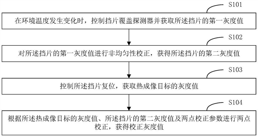
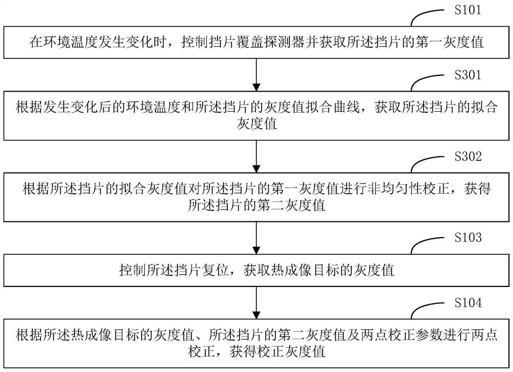
The present application is applicable to the technical field of image processing, and provides a thermal imaging correction method, device and terminal equipment. In the embodiment of the present application, when the ambient temperature changes, the shutter is controlled to cover the detector and the first gray value of the shutter is obtained; the first gray value of the shutter is corrected for non-uniformity to obtain the The second gray value of the shutter; control the reset of the shutter to obtain the gray value of the thermal imaging target; according to the gray value of the thermal imaging target, the second gray value of the shutter and two points The correction parameters are corrected at two points to obtain the corrected gray value, which can correct the responsivity of different detection units to the same and eliminate the non-uniformity of the image, and make the corrected gray value applicable to each temperature range within the temperature measurement range, thereby Improve imaging stability.

Description

technical field [0001] The present application belongs to the technical field of image processing, and in particular relates to a thermal imaging correction method, device and terminal equipment. Background technique [0002] With the continuous development of infrared sensing technology, the accuracy of temperature detection and imaging clarity of thermal imaging equipment has been greatly improved, and it has been widely used in various fields such as fire protection, medical treatment, and security. [0003] Thermal imaging equipment is very sensitive to changes in ambient temperature. When the ambient temperature is too low relative to the temperature of the thermal imaging target, the grayscale value will be oversaturated and the image will become white. When the ambient temperature is too high relative to the temperature of the thermal imaging target, the grayscale value will If the value is too low, the brightness of the image will be too dark, which will cause the te...

Claims


Application Information

Patent Timeline
Patent Type & Authority Patents(China)
IPC IPC(8): G01J5/48G01J5/90G06T5/00
CPCG01J5/00G06T5/007G01J2005/0077G01J5/80
Inventor 刘明王彬吴汉俊
Owner 深圳市景阳信息技术有限公司
Learn More