Imaging method and imaging device of microlens array

An imaging method and technology of an imaging device, which are applied in the direction of image communication, color TV parts, TV system parts, etc., can solve problems such as uneven brightness distribution, achieve a wide range of applications, and eliminate adverse effects

Active Publication Date: 2020-04-03
SUPERD CO LTD
View PDF5 Cites 0 Cited by
  • Summary
  • Abstract
  • Description
  • Claims
  • Application Information

AI Technical Summary

Problems solved by technology

[0003] In view of the above technical problems, the present invention provides an imaging method and an imaging device of a microlens array, which solves the problem of uneven brightness distribution in the original image formed by the microlens array, improves the quality of the original image, and reduces the impact on the image formed by the microlens. Difficulty doing matching and splicing

Method used


Image

  • Imaging method and imaging device of microlens array
  • Imaging method and imaging device of microlens array
  • Imaging method and imaging device of microlens array

Examples


no. 1 example

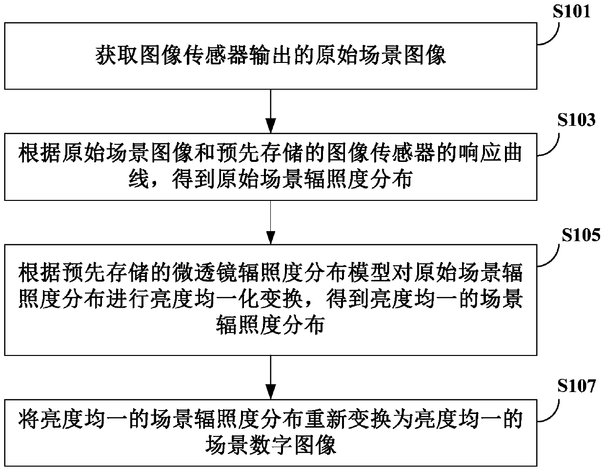
[0062] see figure 1 , the figure shows the flow chart of the imaging method of the microlens array of the first embodiment, the method can be applied to light field cameras, compound eye cameras and microscopic imaging systems of large field of view, the specific steps included in the method are as follows:

[0063] Step S101, acquiring the original scene image output by the image sensor.

[0064] Specifically, a microlens array is used to shoot an actual scene to obtain an original scene image. Preferably, the scene can be photographed multiple times with different exposure times to obtain multiple original scene images with different exposure times.

[0065] Step S103 , according to the original scene image and the pre-stored response curve of the image sensor, the original scene irradiance distribution is obtained.

[0066] It should be noted that in order to eliminate the adverse effects of the nonlinear response of the image sensor to illumination, it is necessary to re...

no. 2 example

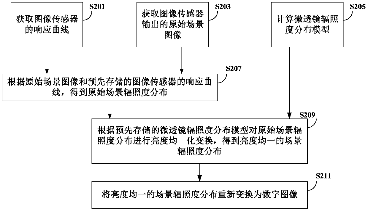
[0073] see figure 2 , is a flow chart of the imaging method of the microlens array according to the second embodiment of the present invention. The method can be applied to light field cameras, compound eye cameras and microscopic imaging systems with large fields of view. The specific steps included in the method are as follows:

[0074] Step S201. Obtain the response curve of the image sensor, and store the response curve of the image sensor in a storage device, and then enter step S207.

[0075] Step S203, acquire the original scene image output by the image sensor, and then enter step S207.

[0076] Specifically, the microlens array is used to shoot the actual scene to obtain the original scene image. Preferably, the scene may be photographed multiple times with different exposure times to obtain multiple original scene images with different exposure times.

[0077] Step S205, calculate the microlens irradiance distribution model, and then enter step S209.

[0078] Spec...

no. 3 example

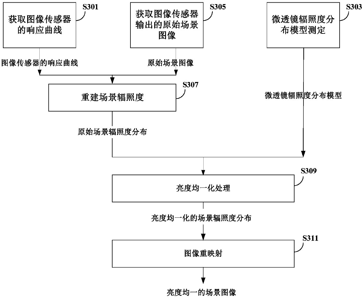
[0105] see image 3 , the figure shows the flow chart of the microlens array imaging method of the third embodiment of the present invention, the method can be applied to light field cameras, compound eye cameras and microscopic imaging systems with large field of view, the specific steps included in the method as follows:

[0106] Step S301, acquiring a response curve of an image sensor.

[0107] It should be noted that the response curve of the image sensor expresses the nonlinear mapping relationship in which the sensor converts the radiation amount of light into a digital image value, which is an inherent characteristic of the sensor. The acquisition of the response curve can be carried out when the image sensor is finalized, and the response curve of the sensor can be obtained by searching the factory parameters of the sensor; if the response curve data is lacking, the response curve of the image sensor can also be measured experimentally. The experimental measurement me...


PUM


Abstract

The present invention provides an imaging method and an imaging device of a microlens array. The imaging method includes: obtaining an original scene image output by an image sensor; Scene irradiance distribution; according to the pre-stored microlens irradiance distribution model, perform brightness uniform transformation on the original scene irradiance distribution to obtain a scene irradiance distribution with uniform brightness; convert the scene irradiance distribution with uniform brightness to The illuminance distribution is re-transformed into a digital image of the scene with uniform brightness, which solves the problem of uneven brightness distribution in the original image formed by the microlens array, improves the quality of the original image, and reduces the difficulty of matching and splicing the image formed by the microlens.

Description

technical field [0001] The invention relates to the field of imaging technology, in particular to an imaging method and an imaging device of a microlens array. Background technique [0002] Microlens arrays are widely used in light field cameras, compound eye cameras, and microscopic cameras with large fields of view. However, due to the fluctuation of light and the non-linear response of the image sensor in the processes of light sensing, conversion of analog signals to digital signals, and remapping of digital signals to digital images, the illumination distribution in the output digital image is different from the real one. The ambient light distribution of the scene is not linear, which leads to the non-uniformity of the brightness in the microlens imaging, resulting in the phenomenon that each microlens imaging will appear bright in the middle and dark around. This will cause serious interference to the subsequent processing of microlens array imaging (whether it is ma...

Claims


Application Information

Patent Timeline
Patent Type & Authority Patents(China)
IPC IPC(8): H04N5/235H04N5/238
CPCH04N23/71H04N23/73H04N23/75
Inventor 杨青郁树达
Owner SUPERD CO LTD
Why Eureka
Try Eureka