
Plane contour grinding center of door-shaped vertical mill

A technology of plane profile and grinding center, which is applied in the direction of machine tools, grinding racks, and grinding beds suitable for grinding workpiece planes, and can solve problems such as inconvenient use and low efficiency of grinding wheel dressing

Pending Publication Date: 2021-05-11
豪特曼智能装备信阳有限公司
View PDF0 Cites 4 Cited by
  • Summary
  • Abstract
  • Description
  • Claims
  • Application Information

AI Technical Summary

Problems solved by technology

In the prior art, the disadvantages of surface grinders are 1. When grinding special workpieces or irregular workpieces, it is often necessary to replace emery wheels of different specifications multiple times. Each time the emery wheel is replaced, it is necessary to manually disassemble the emery wheel, which is inconvenient to use; 2. After the grinding wheel has been used for a long time, it needs to be trimmed. When trimming, it is necessary to manually disassemble the grinding wheel from the surface grinder, then install the grinding wheel on the grinding wheel dresser for dressing, and then remove the trimmed grinding wheel from the grinding wheel. The grinding wheel is disassembled on the dressing, and finally the grinding wheel is put back on the surface grinder. The whole process requires manual disassembly and assembly of the grinding wheel twice, and the dressing efficiency of the grinding wheel is low.

Method used


Image

  • Plane contour grinding center of door-shaped vertical mill
  • Plane contour grinding center of door-shaped vertical mill
  • Plane contour grinding center of door-shaped vertical mill

Examples


Embodiment Construction

[0025] The present invention will be further described below in conjunction with accompanying drawing:

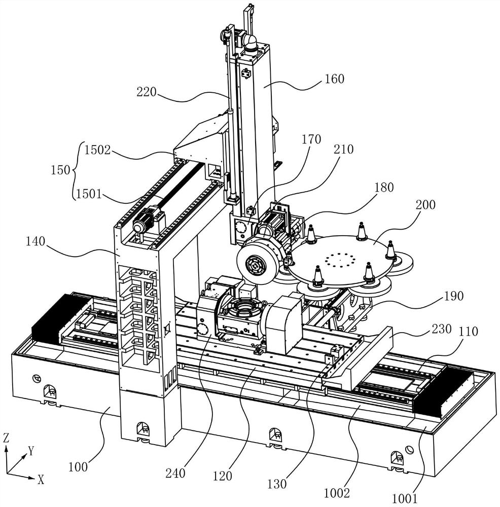
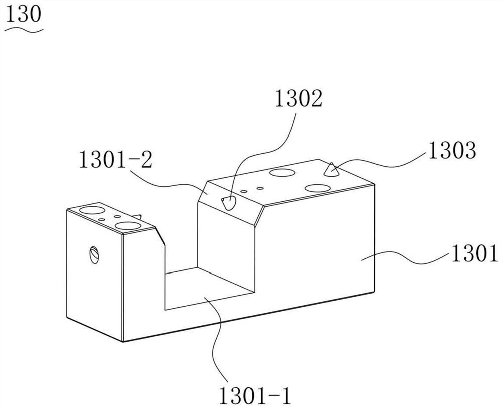
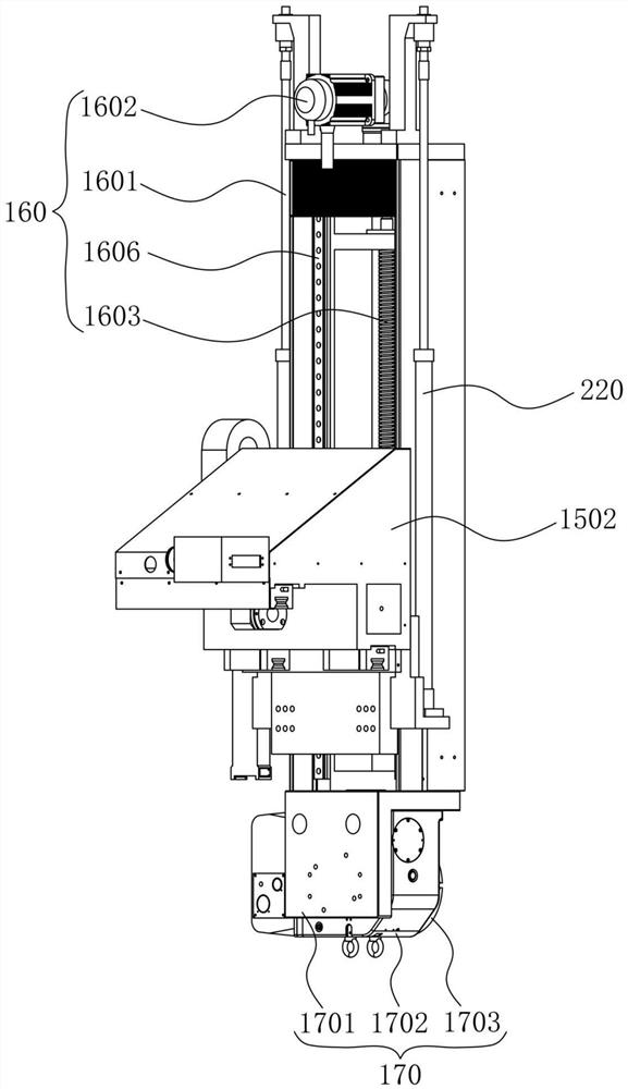
[0026] Please refer to figure 1 , a gantry-type vertical grinding plane profile grinding center, including a cross-shaped bed 100, an X-axis feed device 110, a workbench 120, a sand repair device 130, a gantry frame 140, and a Y-axis feed device 150 , Z axial feed device 160, automatic angle adjustment device 170, automatic tool change electric spindle 180, Y axial drive device 190 and grinding wheel tool magazine 200, X axial feed device 110 is installed on the bed 100, the workbench 120 is installed on the X-axis feeding device 110, the sand repairing device 130 is installed on the workbench 120, the gantry frame 140 is installed on the bed 100, the Y-axis feeding device 150 is installed on the gantry frame 140, and the Z-axis The feed device 160 is installed on the Y-axis feed device 150, the automatic angle adjustment device 170 is installed on the Z-axis feed device 1...


PUM


Abstract

The invention provides a plane contour grinding center of a door-shaped vertical mill. The plane contour grinding center comprises a lathe bed, an X-axis feeding device, a workbench, a sand finishing device, a portal frame, a Y-axis feeding device, a Z-axis feeding device, an automatic angle adjusting device, an automatic tool changing electric spindle, a Y-axis driving device and a grinding wheel tool magazine. The X-axis feeding device is mounted on the lathe bed; the workbench is installed on the X-axis feeding device, the sand finishing device is installed on the workbench, the portal frame is installed on the lathe bed, the Y-axis feeding device is installed on the portal frame, the Z-axis feeding device is installed on the Y-axis feeding device, the automatic angle adjusting device is installed on the Z-axis feeding device, and the automatic tool changing electric spindle is installed on the automatic angle adjusting device; and the Y-axis driving device is installed on one side of the lathe bed in the Y-axis direction, and the grinding wheel tool magazine is installed on the Y-axis driving device. The plane contour grinding center can automatically complete grinding wheel replacement work, is convenient to use, can also automatically complete grinding wheel dressing work, and is high in dressing efficiency.

Description

technical field [0001] The invention relates to the field of grinding machines, in particular to a plane profile grinding center of a door-type vertical mill. Background technique [0002] The surface grinder grinds the surface of the workpiece by driving the grinding wheel to rotate at high speed, so that the workpiece can reach the required precision. In the prior art, the disadvantages of surface grinders are 1. When grinding special workpieces or irregular workpieces, it is often necessary to replace emery wheels of different specifications multiple times. Each time the emery wheel is replaced, the emery wheel needs to be manually disassembled, which is inconvenient to use; 2. After the grinding wheel has been used for a long time, it needs to be trimmed. When trimming, it is necessary to manually disassemble the grinding wheel from the surface grinder, then install the grinding wheel on the grinding wheel dresser for dressing, and then remove the trimmed grinding wheel ...

Claims


Application Information

Patent Timeline
IPC IPC(8): B24B7/10B24B41/00B24B47/20B24B41/04B24B45/00B24B53/06B24B53/12B24B41/02B24B47/22
CPCB24B7/10B24B41/00B24B47/20B24B41/04B24B45/003B24B53/06B24B53/12B24B41/02B24B47/22
Inventor 曾俊范伟奇
Owner 豪特曼智能装备信阳有限公司
Learn More