Rod-shaped piezoelectric material mounting equipment

A piezoelectric material, technology for installing equipment, applied in the field of piezoelectric materials

Inactive Publication Date: 2021-05-11
谢美芬
View PDF0 Cites 0 Cited by
  • Summary
  • Abstract
  • Description
  • Claims
  • Application Information

AI Technical Summary

Problems solved by technology

[0003] Because the rod-shaped piezoelectric material will generate charge and voltage at both ends after being squeezed, if the rod-shaped piezoelectric material is subjected to a greater pressure, the generated charge will increase proportionally, which will cause the rod-shaped piezoelectric material to press into the The top of the device is easily attached to the inner wall of the indenter due to the charge carried by the indenter and is brought out of the piezoelectric device by the indenter

Method used


Image

  • Rod-shaped piezoelectric material mounting equipment
  • Rod-shaped piezoelectric material mounting equipment
  • Rod-shaped piezoelectric material mounting equipment

Examples


Embodiment 1

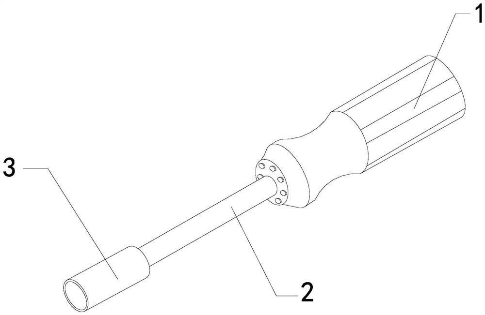
[0026] For example figure 1 -example Figure 5 Shown:

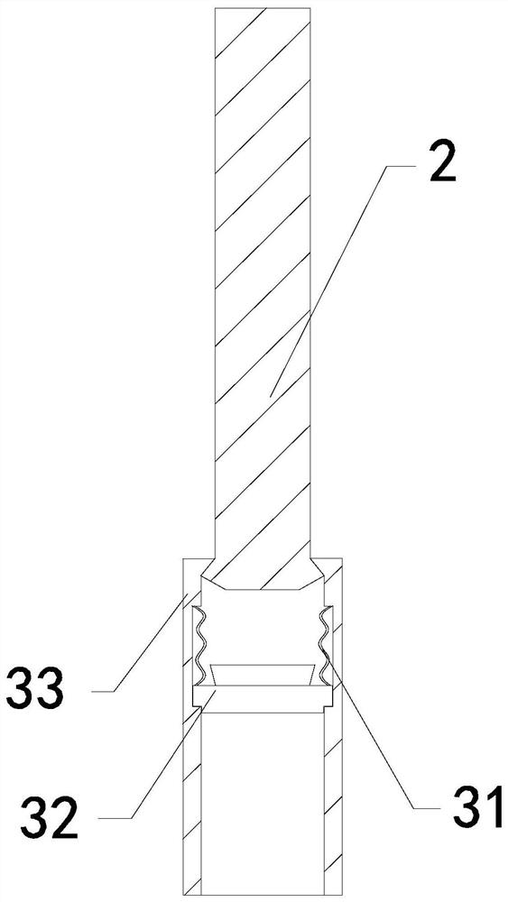
[0027] The invention provides a rod-shaped piezoelectric material installation device, the structure of which includes a handle 1, a linkage rod 2, and a press-in head 3. The linkage rod 2 is embedded in the inner position of the handle 1. The press-in head 3 and the linkage rod The bottom of 2 is welded; the press-in head 3 includes a booster bar 31, a pressure plate 32, and an outer frame 33, and the booster bar 31 is installed between the upper end of the pressure plate 32 and the inner wall of the outer frame 33, The pressure receiving plate 32 is movably engaged with the inside of the outer frame 33 .

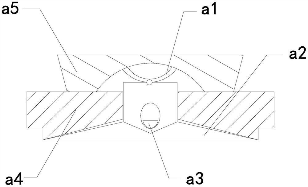
[0028] Wherein, the pressure receiving plate 32 includes an elastic piece a1, a lower stretching plate a2, a vibrating block a3, a receiving plate a4, and a top plate a5. Between the upper ends, the lower extension plate a2 is in sliding fit with the interior of the receiving plate a4, the vibrating mass a3 is matc...

Embodiment 2

[0034] For example Figure 6 -example Figure 8 Shown:

[0035] Wherein, the linkage rod 2 includes an connecting plate c1, a sliding rod c2, a connection bar c3, and a push-down block c4. The inner position of the board c1, the push-down block c4 is embedded and fixed at the bottom position of the sliding rod c2, and the two connecting strips c3 are arranged symmetrically on the left and right sides of the sliding rod c2. The electric strip c3 can lead out the electric charge conducted on the sliding rod c2.

[0036]Wherein, the push-down block c4 includes a position fixing plate c41, a side sliding plate c42, a sliding aid mechanism c43, and a pull-back bar c44. The side sliding plate c42 is movably engaged with the bottom of the positioning fixing plate c41. Embedded in the inner position of the side slide c42, the pull-back strip c44 is installed between the side slide c42 and the inner wall of the position fixing plate c41, the side slide c42 is provided with two, and ...


PUM


Abstract

The invention discloses rod-shaped piezoelectric material mounting equipment which structurally comprises a handle, a linkage rod and a press-in head. The linkage rod is embedded in the handle, the press-in head is welded to the bottom of the linkage rod, and when a pressed plate is attracted by voltage generated by the top of a rod-shaped piezoelectric material, the rod-shaped piezoelectric material pulls a downward extending plate, so that the downward extending plate extends out downwards along a bearing plate under the cooperation of an elastic sheet; electric charges between the rod-shaped piezoelectric material and the downward extending plate can be guided into an electric lead wire through a conductive block and then are guided out through the electric lead wire to be eliminated; and the electric charges on the pressed plate can be guided out to the two sides through a power connection strip by means of the cooperation of a lower push block and a sliding rod, and the top of the pressed plate can generate reverse thrust between two side sliding plates through the pressure generated by the weight of the lower push block on the top of the pressed plate, so that the side sliding plates can push the pressed plate away downwards.

Description

technical field [0001] The invention relates to the field of piezoelectric materials, in particular to a rod-shaped piezoelectric material installation device. Background technique [0002] The rod-shaped piezoelectric material indenter is mainly used to press the rod-shaped piezoelectric material into the piezoelectric device. The indenter of the rod-shaped piezoelectric material indenter can be set on the rod-shaped piezoelectric material. , and then press the rod-shaped piezoelectric material into the piezoelectric device by pushing the handle, and the two ends of the rod-shaped piezoelectric material will generate charges and voltages when being squeezed. Based on the above description, the inventors found that an existing Rod-shaped piezoelectric material installation equipment mainly has the following deficiencies, such as: [0003] Because the rod-shaped piezoelectric material will generate charge and voltage at both ends after being squeezed, if the rod-shaped piezo...

Claims


Application Information

Patent Timeline
Patent Type & Authority Applications(China)
IPC IPC(8): B25B27/02
CPCB25B27/02
Inventor 刘雪霞
Owner 谢美芬
Why Eureka
Try Eureka