Storage equipment for polypropylene

A storage device, polypropylene technology, applied in the direction of internal accessories, external accessories, etc., can solve the problems of polyethylene particles sticking together, and polypropylene particles being too late to dissipate heat completely.

Inactive Publication Date: 2021-02-19
钱立超
View PDF0 Cites 0 Cited by
  • Summary
  • Abstract
  • Description
  • Claims
  • Application Information

AI Technical Summary

Problems solved by technology

[0003] Since the inside of the polypropylene storage tank is a closed space, and the polypropylene granules are shaped and cut after the polypropylene is melted at high temperature, if the polypropylene granulator extrudes the polypropylene at a faster speed, the internal heat of the polypropylene granules will There is not enough time to dissipate heat completely, causing the polyethylene particles on the bottom layer inside the polypropylene storage tank to stick together

Method used


Image

  • Storage equipment for polypropylene
  • Storage equipment for polypropylene
  • Storage equipment for polypropylene

Examples


Embodiment 1

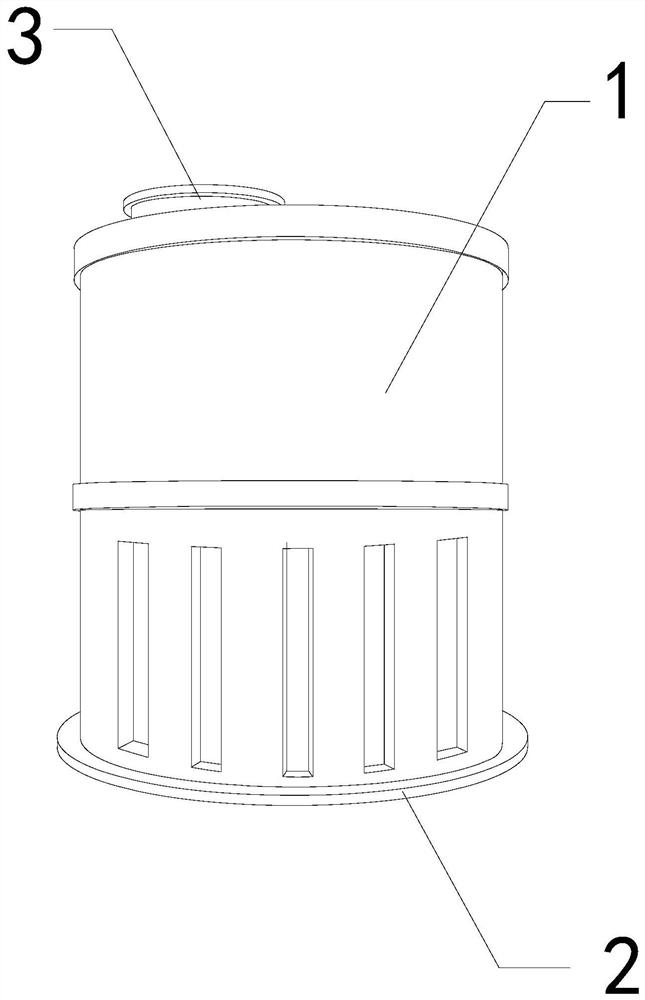
[0026] For example figure 1 -example Figure 5 Shown:

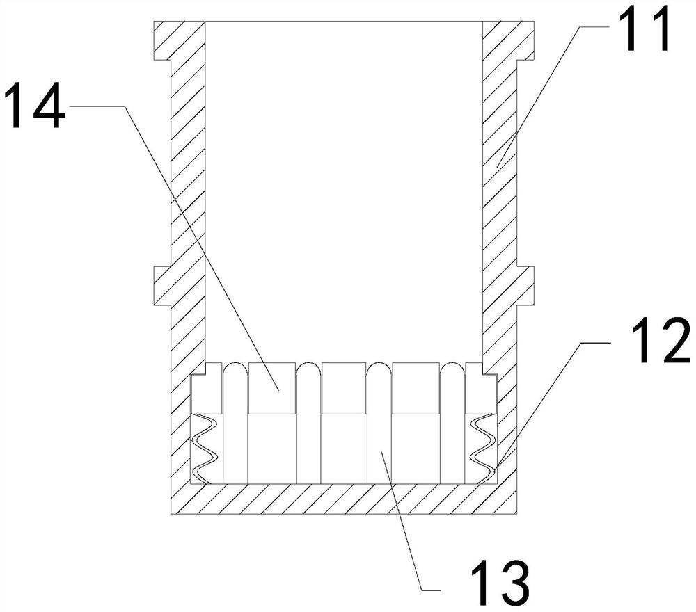
[0027] The invention provides a storage device for polypropylene, the structure of which includes a storage bucket 1, a base 2, and a feed port 3. The feed port 3 is embedded in the upper end of the storage bucket 1. phase welding; the storage bucket 1 includes an outer frame 11, an elastic strip 12, an upper extension plate 13, and a contraction plate 14. The bottom of 13 is embedded and connected with the bottom of the inner wall of the outer frame 11 , and the upper extension plate 13 is in clearance fit with the contraction plate 14 , and the contraction plate 14 is movably engaged with the outer frame 11 .

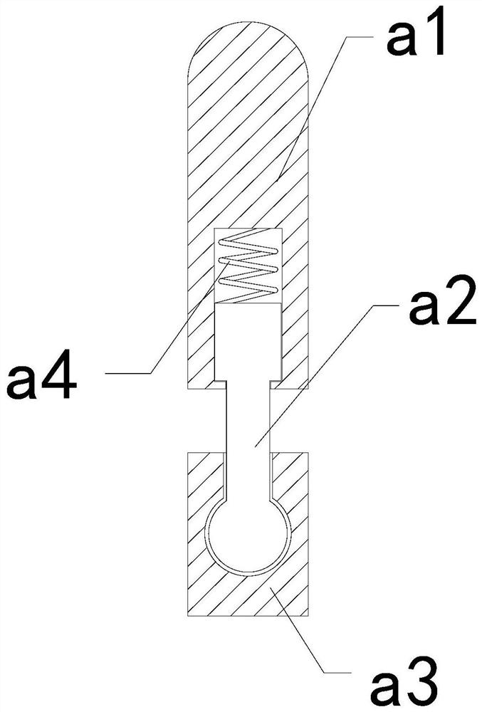
[0028] Wherein, the upper extension plate 13 includes a contact plate a1, a middle solid bar a2, a bottom plate a3, and a booster bar a4, the contact plate a1 is connected with the middle solid bar a2, and the middle solid bar a2 is movable with the bottom plate a3 Together, the booster bar a4 is installed bet...

Embodiment 2

[0034] For example Figure 6 -example Figure 8 Shown:

[0035] Wherein, the connecting plate a11 includes a receiving plate c1, a heat sink c2, and a heat conduction mechanism c3. The heat sink c2 and the heat conduction mechanism c3 are an integrated structure, and the heat conduction mechanism c3 is embedded in the inner position of the receiving plate c1. The receiving plate c1 is made of copper metal with strong thermal conductivity, and the heat inside the object can be introduced into the interior of the heat conducting mechanism c3 through c4.

[0036] Wherein, the heat conduction mechanism c3 includes a frame c31, an upper sliding ball c32, an interference plate c33, and a reverse push bar c34. The upper slide ball c32 is installed in the inner position of the frame c31, and the interference plate c33 is embedded in the reverse push bar. The bottom position of c34, the reverse push bar c34 is connected with the upper end of the inner wall of the frame c31, and the t...


PUM


Abstract

The invention discloses a storage device for polypropylene. The storage device for the polypropylene structurally comprises a storage barrel, a base and a feeding port, wherein the feeding port is fixedly embedded in the upper end of the storage barrel; and the storage barrel is welded to the base. A middle fixing rod drives a contact plate to rotate to generate throwing force, separation blocks can scatter polypropylene particles adhered to a bottom layer in the storage barrel along with the rotation of the middle fixing rod, so that the situation that the polypropylene particles at the bottom layer in the storage barrel are adhered together due to heat which cannot be dissipated in time is effectively avoided; and through the thrust of the inner wall of a frame against a flow increasingplate, the flow increasing plate can contract inwards along a built-in ring under the cooperation of a transition rod, and then the flow increasing plate can stretch out and draw back repeatedly through the cooperation of elastic pieces, so that the heat dissipation speed of heat on a bearing plate can be increased through airflow generated by the flow increasing plate, and the situation that thepolypropylene particles are adhered together again due to the heat of the polypropylene particles is effectively avoided.

Description

technical field [0001] The invention relates to the field of polypropylene equipment, in particular to a storage equipment for polypropylene. Background technique [0002] The polypropylene storage tank is mainly used to store polypropylene materials. By placing the plastic at the outlet of the polypropylene granulator, the polypropylene particles can be collected inside the polypropylene storage tank. Common equipment, based on the above description, the inventors found that the existing storage equipment for polypropylene mainly has the following deficiencies, for example: [0003] Since the inside of the polypropylene storage tank is a closed space, and the polypropylene granules are shaped and cut after the polypropylene is melted at high temperature, if the polypropylene granulator extrudes the polypropylene at a faster speed, the internal heat of the polypropylene granules will There is not enough time to dissipate heat completely, which leads to a situation where the...

Claims


Application Information

Patent Timeline
Patent Type & Authority Applications(China)
IPC IPC(8): B65D25/02B65D25/24B65D25/20
CPCB65D25/02B65D25/20B65D25/24
Inventor 钱立超
Owner 钱立超
Why Eureka
Try Eureka