Excavator forearm and excavator

A technology for excavators and booms, applied in the field of excavators, can solve the problems of high energy consumption, low energy utilization rate of excavators, lack of structure and technical solutions, etc.

Pending Publication Date: 2021-05-11
董志强
View PDF0 Cites 1 Cited by
  • Summary
  • Abstract
  • Description
  • Claims
  • Application Information

AI Technical Summary

Problems solved by technology

Nowadays, energy shortages and environmental pollution problems are becoming more and more serious, and research and development of energy-saving excavators has become a trend. However, due to the large mass of excavator arm mechanisms, this requires a lot of energy consumption, and most of the energy cannot be used for effective work. , so the energy utilization rate of the excavator is very low. To solve the problem of large mass of the arm mechanism of the excavator, it is mainly solved by adopting energy storage technology for the arm mechanism, but the energy storage technology can only solve the problem of lifting the boom. The problem of energy consumption, and how to reduce the energy consumption of booms such as excavator arms, there is still a lack of complete and specific structural and technical solutions

Method used


Image

  • Excavator forearm and excavator
  • Excavator forearm and excavator
  • Excavator forearm and excavator

Examples


Embodiment 1

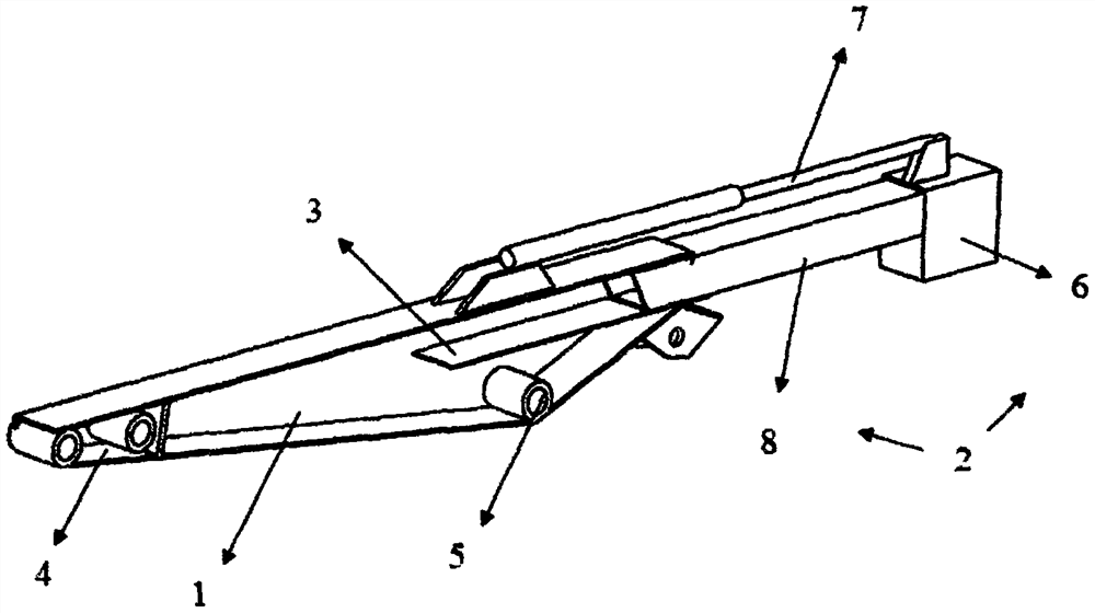
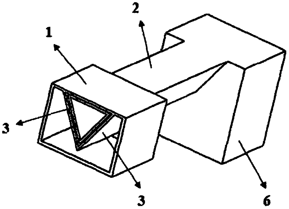
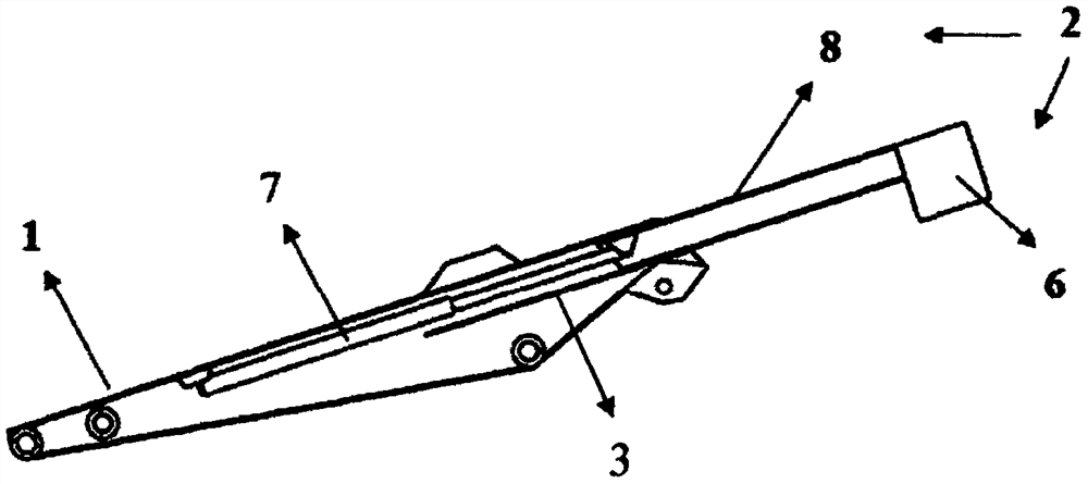
[0052] see figure 1 , figure 2 , image 3 , Figure 4 , a small arm of an excavator, including a forearm body 1, a rear arm body 2, a support plate 3 and a telescopic cylinder 7, the forearm body 1 includes a front end connecting portion 4 and a small arm spindle hole 5, and the front end connecting portion 4 is arranged on the forearm body 1 The front end of the front end, the front end connecting part 4 is used to connect the working device of the excavator, such as working devices such as buckets and extended sleeve arms, the forearm main shaft hole 5 is arranged on the front arm body 1 arm body behind the front end connecting part 4 position, and the forearm body 1 wraps around The forearm body 1 of the forearm of the forearm of the excavator is composed of high-strength plates such as the top plate, the middle side plate, and the bottom plate through welding to form a box structure with a cavity inside. When manufacturing the forearm body 1, The support plate 3 is wel...

Embodiment 2

[0055] see Figure 5 , the counterweight 6 includes a counterweight frame 6a and a counterweight 6b, the counterweight 6b includes a first counterweight 6b1 and a second counterweight 6b2, the counterweight frame 6a is an arm structure, and the tail of the rear arm 8 is connected to the counterweight In the middle of the frame 6a, one end of the counterweight frame 6a is connected to the first counterweight 6b1, and the other end of the counterweight frame 6a is connected to the second counterweight 6b2; because there are many working devices installed directly under the range of movement of the tail of the arm of the existing excavator , such as hydraulic pipelines, electrical circuits, oil cylinders, valve bodies, etc., the width of these devices after installation is close to the width of the forearm. This embodiment can prevent the counterweight 6 from touching these when the rear arm body 2 moves downward. device.

[0056] In this embodiment, the form of the counterweigh...

Embodiment 3

[0059] see Figure 7 , the counterweight frame 6a includes a first counterweight arm 6a1, a second counterweight arm 6a2 and a third counterweight arm 6a3, the counterweight 6b includes a first counterweight 6b1 and a second counterweight 6b2, and the tail of the rear arm 8 Connect the middle part of the first counterweight arm 6a1, one end of the first counterweight arm 6a1 is connected to the upper end of the second counterweight arm 6a2, the other end of the first counterweight arm 6a1 is connected to the upper end of the third counterweight arm 6a3, and the lower end of the second counterweight arm 6a2 is connected to The lower end of the first counterweight 6b1 and the third counterweight arm 6a3 is connected to the second counterweight 6b2. This structure moves the position of the counterweight down, lowering the overall center of gravity of the arm, thereby improving the symmetry between the power arm and the resistance arm , to further reduce the energy consumption of ...


PUM


Abstract

The invention discloses an excavator forearm and an excavator. The excavator forearm comprises a forearm body, a cavity is formed inside the forearm body, the excavator forearm further comprises a bearing plate, the bearing plate is arranged in the inner cavity of the forearm body, the bearing plate is connected with the forearm body to form a slide way inside the forearm body in the length direction of the forearm body, the tail part of the forearm body is provided with an opening hole communicating with the slide way inside the forearm body, the excavator forearm further comprises a rear arm body, the rear arm body comprises a counterweight and a rear arm, the counterweight is arranged at the rear part of the rear arm, the front end of the rear arm is inserted into the slide way inside the forearm body from the opening hole in the tail part of the forearm body, the excavator forearm further comprises a telescopic cylinder, one end of the telescopic cylinder is connected with the forearm body, and the other end of the telescopic cylinder is connected with the rear arm body. The excavator forearm and the excavator are compact and reasonable in structure, low in manufacturing cost and easy to implement.

Description

technical field [0001] The invention relates to the field of excavators, in particular to an excavator arm and an excavator. Background technique [0002] Hydraulic excavator is the main equipment in construction machinery, widely used in industry, civil construction, transportation, water conservancy and electric power engineering, mining and modern military engineering. Nowadays, energy shortages and environmental pollution problems are becoming more and more serious, and research and development of energy-saving excavators has become a trend. However, due to the large mass of excavator arm mechanisms, this requires a lot of energy consumption, and most of the energy cannot be used for effective work. , so the energy utilization rate of the excavator is very low. To solve the problem of large mass of the arm mechanism of the excavator, it is mainly solved by adopting energy storage technology for the arm mechanism, but the energy storage technology can only solve the probl...

Claims


Application Information

Patent Timeline
Patent Type & Authority Applications(China)
IPC IPC(8): E02F3/38E02F3/39E02F3/28
CPCE02F3/28E02F3/369E02F3/38
Inventor 董志强董竞仪
Owner 董志强
Why Eureka
Try Eureka