power transmission mechanism

A technology of power transmission mechanism and output wheel, which is applied in the direction of transmission device, mechanical equipment, friction transmission device, etc., can solve the problems of complexity, large number of parts, and occupying a lot of space, so as to simplify the overall structure, save operating space, and achieve good performance. The effect of the power transmission effect

Active Publication Date: 2022-03-15
UNIVERSAL GLOBAL TECH (HUIZHOU) CO LTD
View PDF6 Cites 0 Cited by
  • Summary
  • Abstract
  • Description
  • Claims
  • Application Information

AI Technical Summary

Problems solved by technology

However, the structural design of the traditional power transmission mechanism is more complex, the number of parts is large and it takes up a lot of space, so there is still room for improvement

Method used


Image

  • power transmission mechanism
  • power transmission mechanism
  • power transmission mechanism

Examples


Embodiment Construction

[0044] The technical content and features of the present invention will be described in detail below through the enumerated embodiments in conjunction with the accompanying drawings. The applicant first explains here that in the entire specification, including the following embodiments and claims, the terms related to direction are all based on the direction in the drawings, but the "upper" mentioned in the content of this specification , "down", "inner", "outer", "top", "bottom", "left", "right", "front", "back" and other directional adjectives are only based on the normal use direction Descriptive terms are examples and are not intended to limit the scope of claims. Secondly, in the embodiments to be described below and in the drawings, the same element numbers represent the same or similar elements or their structural features.

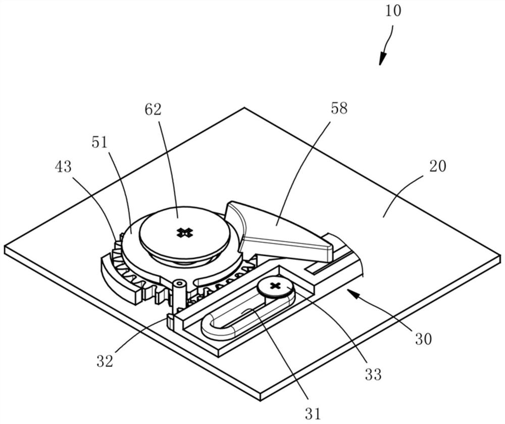
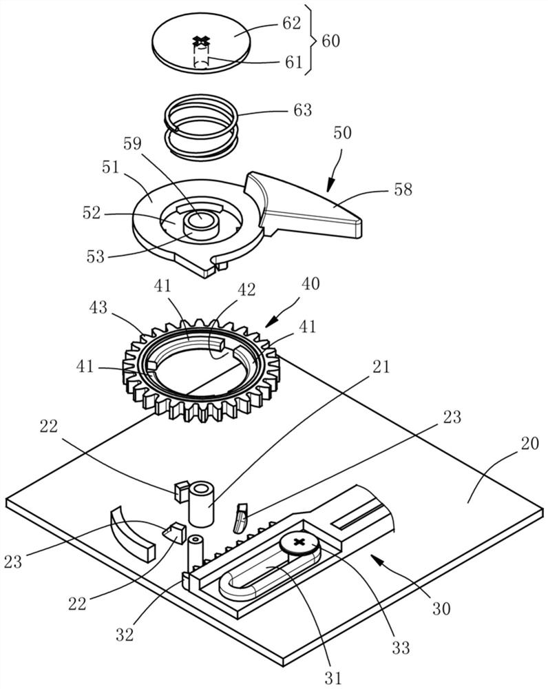
[0045] see figure 1 and figure 2 , The power transmission mechanism 10 of the present invention includes a base 20 , a rack 30 , a ring gear 4...


PUM


Abstract

The invention relates to a power transmission mechanism, which includes a base, a rack, a gear ring and an output wheel; the rack is arranged on the base in a horizontally movable manner, and the gear ring is arranged on the base and engages with the rack , so that the gear ring can be driven by the rack to rotate. The output wheel is set on the base and coaxial with the gear ring. When the output wheel is in the first position, the output wheel will be driven by the gear ring to rotate synchronously. When the output wheel When climbing to the second position, the output wheel will be separated from the gear ring, so that the output wheel can rotate relative to the gear ring; thus, the power transmission mechanism of the present invention can achieve the stroke conversion of input and output, and simplify the overall structural design and save operation space for good power transmission.

Description

technical field [0001] The invention relates to a power transmission mechanism, in particular to a power transmission mechanism with a simplified structure. Background technique [0002] General power transmission mechanisms can be roughly divided into two types: continuous straight-forward type and cyclic reciprocating type. These two types are usually permanently combined in structure. Return to the initial state before cyclic operation. However, the structural design of the traditional power transmission mechanism is relatively complex, with a large number of parts and a large space occupation, so there is still room for improvement. Contents of the invention [0003] The main purpose of the present invention is to provide a power transmission mechanism, which has a simple structure and saves operation space, so as to achieve a good power transmission effect. [0004] In order to achieve the above main purpose, the power transmission mechanism of the present invention...

Claims


Application Information

Patent Timeline
Patent Type & Authority Patents(China)
IPC IPC(8): F16H19/04
CPCF16H19/04
Inventor 刘国光陈勇志陈明仁
Owner UNIVERSAL GLOBAL TECH (HUIZHOU) CO LTD
Why Eureka
Try Eureka