
Micro light-emitting diode display panel

A technology for light-emitting diodes and display panels, applied in electrical components, electric solid-state devices, circuits, etc., can solve the problems of raising the contrast ratio and reducing the panel brightness, and achieve the effect of high contrast ratio, improving color and light contrast, and increasing reflectance ratio.

Pending Publication Date: 2021-05-11
PLAYNITRIDE DISPLAY CO LTD
View PDF7 Cites 0 Cited by
  • Summary
  • Abstract
  • Description
  • Claims
  • Application Information

AI Technical Summary

Problems solved by technology

[0002] In order to increase the contrast ratio of the existing micro-LED display panels, black barriers are filled in the gaps between the micro-LEDs, but this design will greatly reduce the brightness of the panel

Method used


Image

  • Micro light-emitting diode display panel
  • Micro light-emitting diode display panel
  • Micro light-emitting diode display panel

Examples


Embodiment Construction

[0065] Reference will now be made in detail to the exemplary embodiments of the present invention, examples of which are illustrated in the accompanying drawings. Wherever possible, the same reference numbers will be used in the drawings and description to refer to the same or like parts.

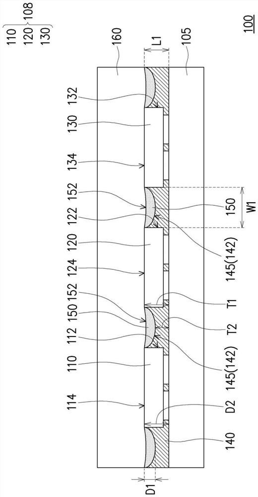
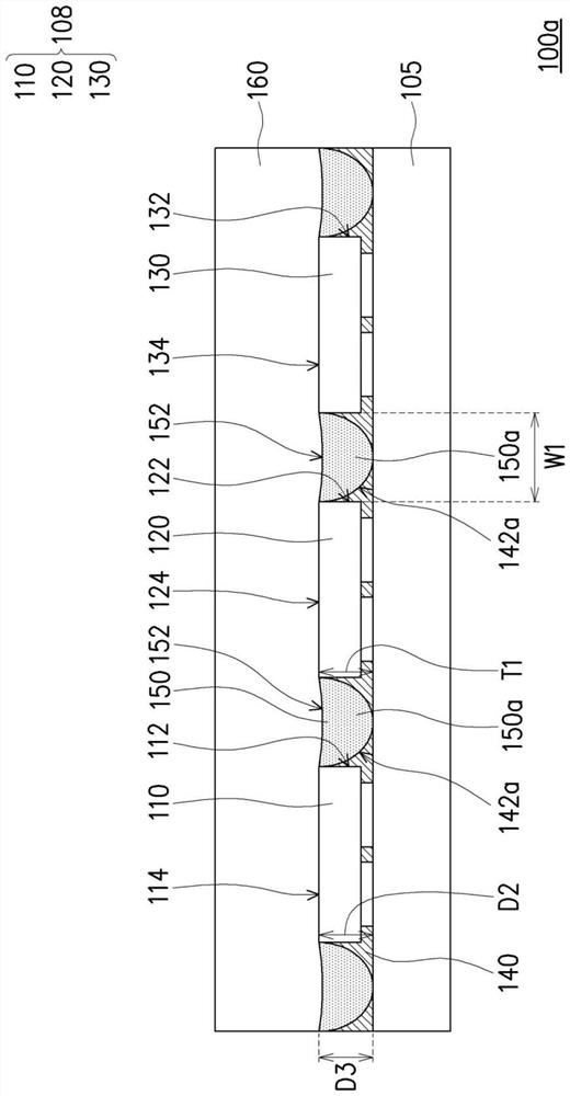
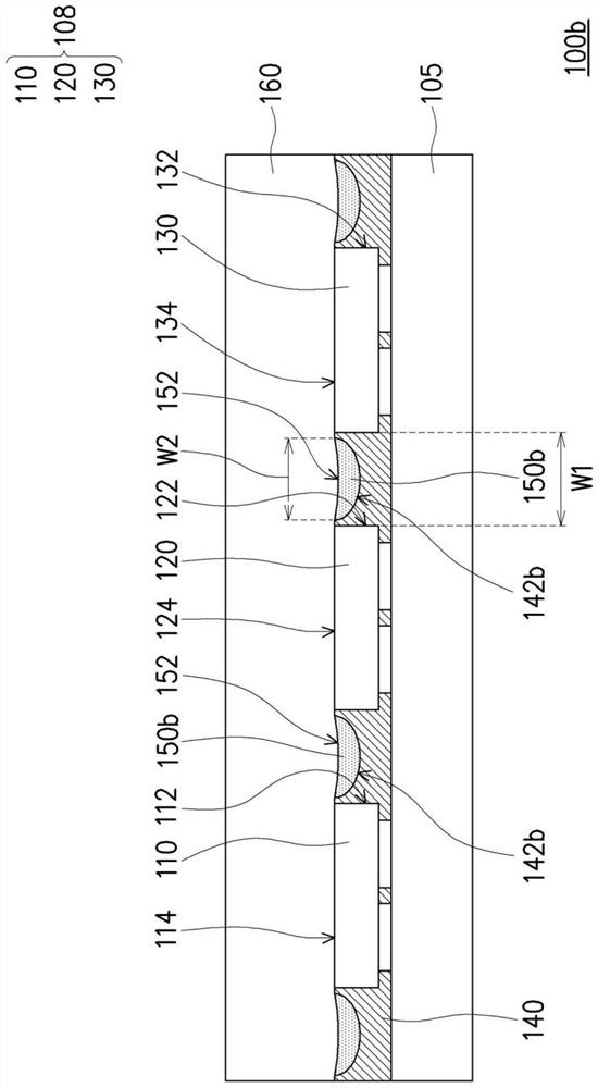
[0066] figure 1 It is a partial cross-sectional schematic diagram of a micro LED display panel according to an embodiment of the present invention. see figure 1, in this embodiment, the micro LED display panel 100 includes a substrate 105 , at least one light emitting unit 108 , a reflective layer 140 and a light absorbing layer 150 .

[0067] At least one light emitting unit 108 is disposed on the substrate 105 to define at least one pixel. exist figure 1 A group of light-emitting units 108 is used as an illustration to define a pixel, but the number of light-emitting units 108 is not limited. In other embodiments, there may be multiple groups of light-emitting units 108, and the plura...


PUM

PropertyMeasurementUnit
absorbanceaaaaaaaaaa
reflectanceaaaaaaaaaa

Abstract

The invention provides a micro light-emitting diode display panel. The display panel comprises a substrate, at least one light-emitting unit, a reflecting layer and a light absorbing layer. The at least one light-emitting unit is arranged on the substrate to define at least one pixel, and each light-emitting unit comprises a plurality of micro light-emitting diodes. The reflecting layer is arranged on the substrate and located between the micro light-emitting diodes, the reflecting layer is provided with a plurality of concave cavities surrounding the micro light-emitting diodes, and the thickness of the reflecting layer close to any micro light-emitting diode is larger than the thickness of the reflecting layer away from the corresponding miniature light-emitting diode. The light absorbing layer is at least arranged in the concave cavities of the reflecting layer. The micro light-emitting diode display panel has high contrast and high brightness.

Description

technical field [0001] The invention relates to a display panel, in particular to a micro light emitting diode display panel. Background technique [0002] In order to increase the contrast ratio of the existing micro-LED display panel, black barriers are filled in the gaps between the micro-LEDs, but this design will greatly reduce the brightness of the panel. Contents of the invention [0003] The invention provides a micro LED display panel with high contrast and high brightness. [0004] A micro light-emitting diode display panel of the present invention includes: a substrate, at least one light-emitting unit, a reflective layer and a light-absorbing layer. At least one light-emitting unit is arranged on the substrate to define at least one pixel, and each light-emitting unit includes a plurality of miniature light-emitting diodes. The reflective layer is disposed on the substrate and is located between each micro-LED, wherein the reflective layer has a plurality of ...

Claims


Application Information

Patent Timeline
Patent Type & Authority Applications(China)
IPC IPC(8): H01L33/58H01L33/60H01L25/075H01L27/15
CPCH01L33/58H01L33/60H01L25/0753H01L27/156
Inventor 孙圣渊骆那登穆鲁根邱柏崴李允立
Owner PLAYNITRIDE DISPLAY CO LTD
Learn More