Automotive lighting device

A technology for motor vehicles and lighting devices, applied in lighting devices, light sources, electric light sources, etc., can solve the problems of harmful lamp drivers, changes in density, changes in light intensity, etc.

Pending Publication Date: 2021-05-11
VALEO VISION SA
View PDF4 Cites 0 Cited by
  • Summary
  • Abstract
  • Description
  • Claims
  • Application Information

AI Technical Summary

Problems solved by technology

In this PWM signal, although the current amplitude is constant, but the density is varied, so that the light intensity of the LED varies
However, this involves the lamp driver being switched on and off many times per second, and this is detrimental to the lamp driver itself and to the rest of the circuit, as electromagnetic radiation is emitted each time the lamp driver is activated
Also, PWM signals require additional systems to generate them

Method used


Image

  • Automotive lighting device
  • Automotive lighting device
  • Automotive lighting device

Examples


Embodiment Construction

[0043] The exemplary embodiments are described in sufficient detail to enable one of ordinary skill in the art to embody and implement the systems and processes described herein. It is important to understand that the embodiments may be provided in many alternative forms and should not be construed as limited to the examples set forth herein.

[0044] Therefore, while the embodiments may be modified in various ways and may take various alternative forms, specific embodiments thereof are shown in the drawings and described in detail below as examples. There is no intention to be limited to the particular forms disclosed. On the contrary, it is intended to embrace all modifications, equivalents, and alternatives falling within the scope of the appended claims. Elements of the exemplary embodiments are referred to by like reference numerals throughout the drawings and applicable detailed description.

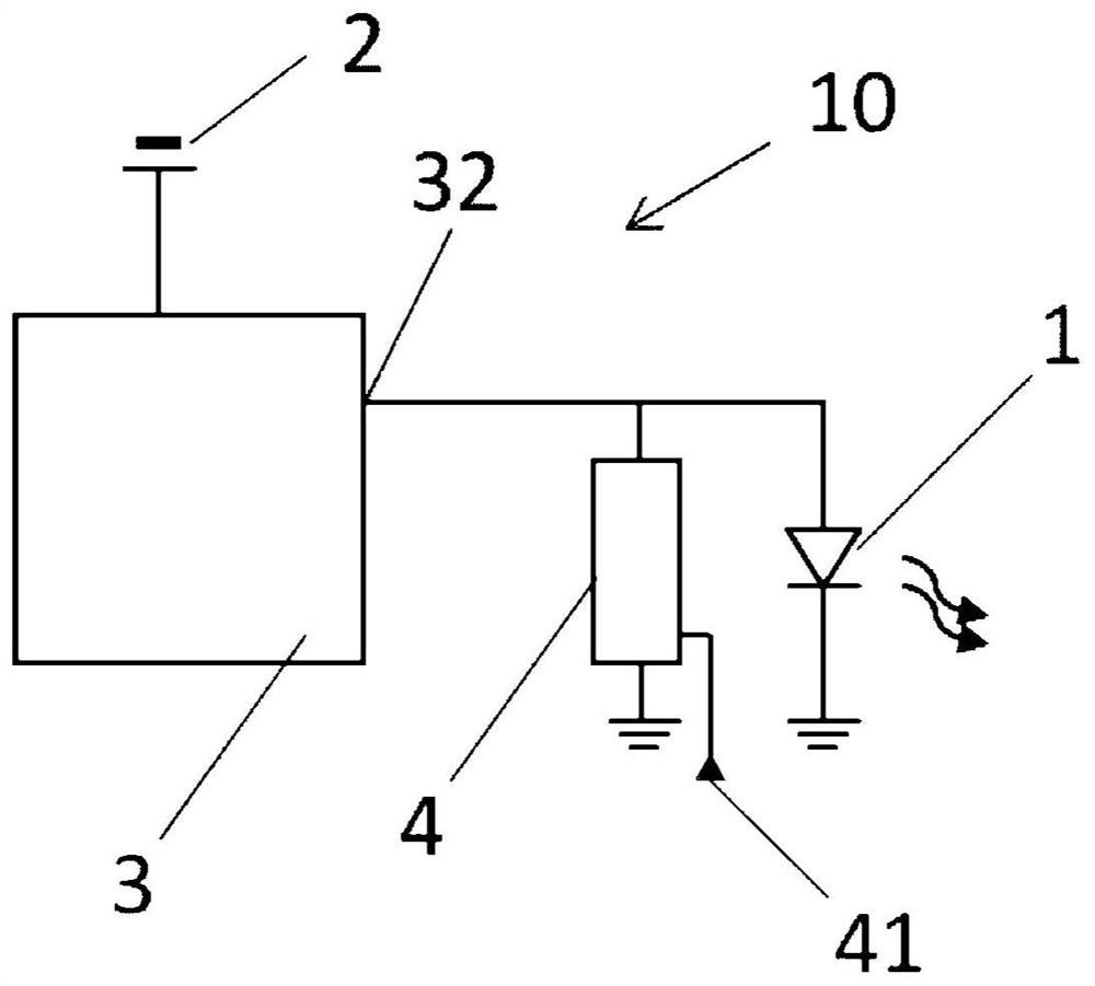
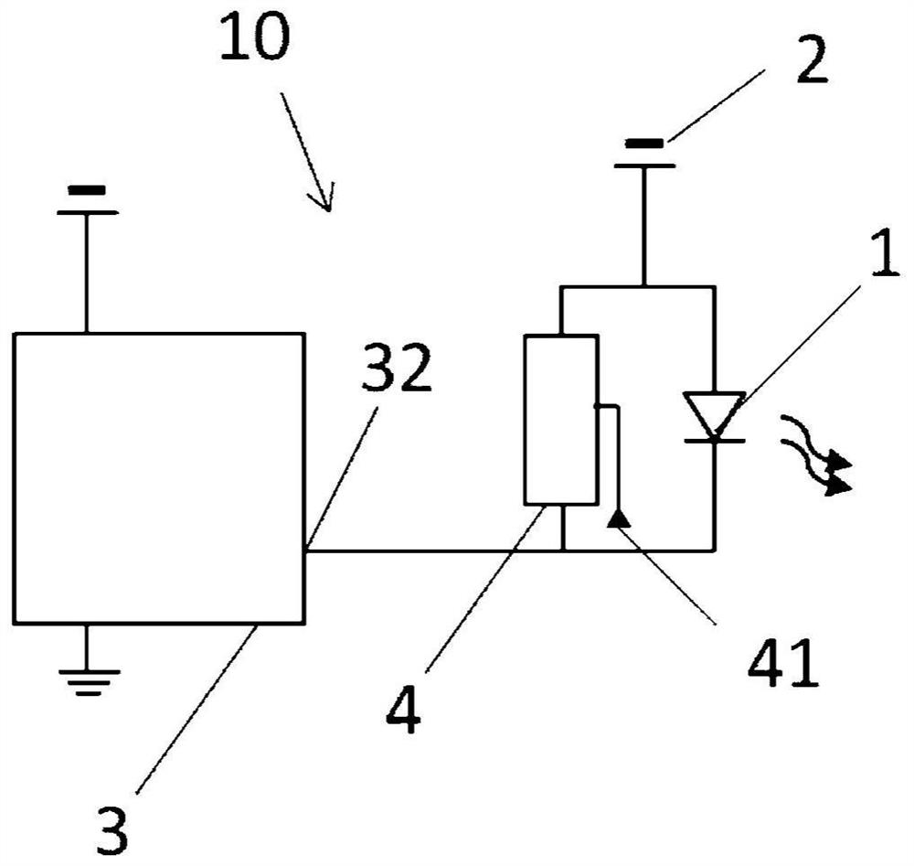
[0045] Figure 1a and Figure 1b The general electrical scheme of the motor...


PUM


Abstract

The invention provides an automotive lighting device (10) for an automotive vehicle (100), the electronic device (10) comprising light sources (1), a current sink device (4) and a light driver (3). The current sink device (4) is in connection with one of the light sources (1), so that each light source with one current sink device forms a light group. The light driver (3) is configured to be electrically fed by the power source (2), the light driver (3) comprising terminals (32) and being configured to selectively activate or deactivate current flow in each terminal (32), in such a way that each light group is connected to one of the terminals. The light driver (3) is located in series with the light groups with respect to the power source (2), either between the power source (2) and the light groups or between the light groups and the ground connection. The current sink device (4) comprises an input (41) configured to receive an activation signal, in such a way that the current sink device (4) is configured to be selectively activated to consume power.

Description

technical field [0001] The invention relates to the field of motor vehicle lighting devices which are controlled to provide complex lighting functions. Background technique [0002] Motor vehicle lighting devices are designed to perform different functions. For this purpose, the lighting device comprises different lighting modules, each of which is responsible for one of the lighting functions. [0003] However, in some cases the device must be simplified or made smaller. As a result, it is sometimes desirable to combine different functions in a single lighting module. These functions are usually grouped by color: since the tracking function and the braking function have the same color, the same lighting module is designed to perform both functions. [0004] In some cases, as shown in the examples above, different functions are defined by different luminous intensities. This problem can sometimes be solved by providing two separate modules: the "brake" function will acti...

Claims


Application Information

Patent Timeline
Patent Type & Authority Applications(China)
IPC IPC(8): H05B45/00H05B45/10H05B45/345H05B47/155H05B44/00
CPCH05B45/48H05B45/46H05B45/44H05B45/397B60Q1/0011H03K17/78
Inventor 约安-乔瑟·圣提埃拉安东尼奥·卡拉维亚约瑟-路易斯·洛佩斯安东尼奥·多明戈·伊兰安赫尔-赫苏斯·科沃
Owner VALEO VISION SA
Why Eureka
Try Eureka