
Turnover table frame and table

A technology of flipping tables and rotating shafts is applied in the field of lifting tables, which can solve the problems of poor stability of table legs, easy to roll over, and small size.

Pending Publication Date: 2021-05-14
NINGBO HAISHIKAI DRIVER TECH CO LTD
View PDF8 Cites 0 Cited by
  • Summary
  • Abstract
  • Description
  • Claims
  • Application Information

AI Technical Summary

Problems solved by technology

[0002] Lifting desks are widely used in Europe and the United States, and are gradually recognized and widely used in China. It can be adjusted in height according to the use situation to achieve the most comfortable state for the human body. The desktop of the existing lifting desks is generally fixed and inconvenient for storage. For People living in the city, housing prices are increasing rapidly, the living space is small, and the lifting table takes up a lot of space, making the whole room appear crowded and narrow
[0003] The traditional reversible table that can be stored includes a table frame and a table top board. The table frame is composed of crossed table legs. The hinge points of the table board and the table frame are fixed. On the side, the tabletop is easy to flap, and the table legs are not stable, so it needs to be leaned against the corner of the wall. When in use, the table legs are unfolded, the tabletop is turned up, and it is placed flat on the table frame. There is no fixing device, and it is easy to roll over and stable. poor sex

Method used


Image

  • Turnover table frame and table
  • Turnover table frame and table
  • Turnover table frame and table

Examples


Embodiment 1

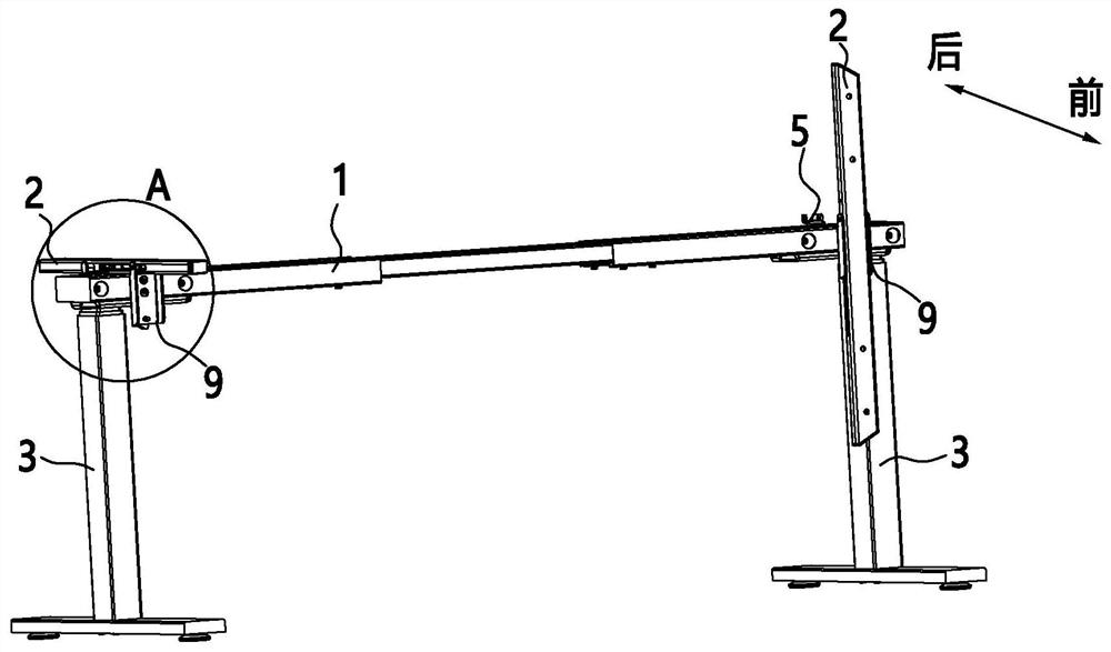
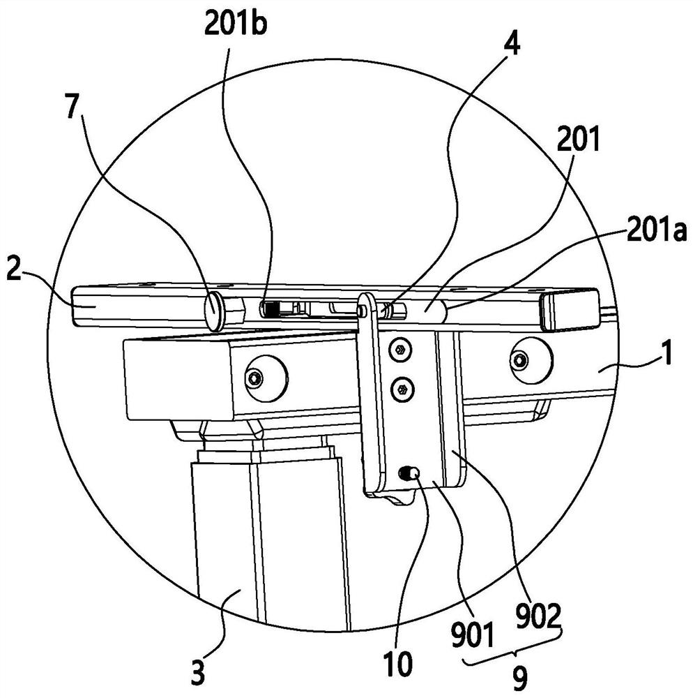
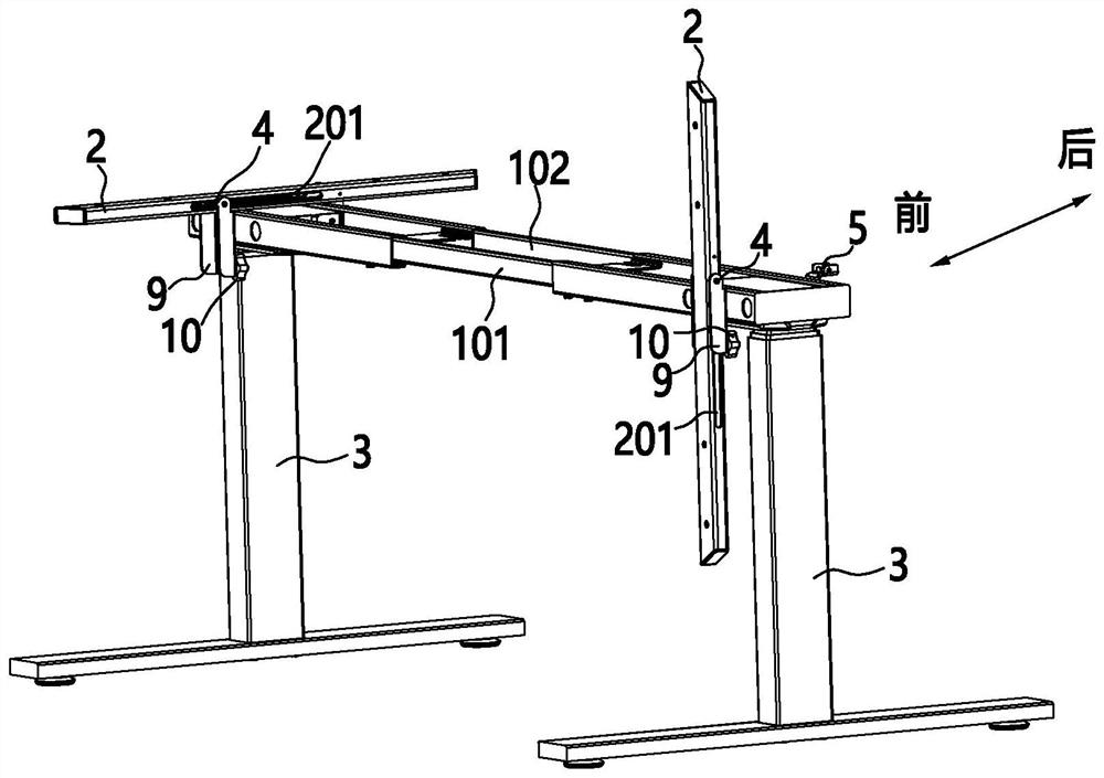
[0036] Such as Figure 1 to Figure 7 As shown, a flip table frame includes a lifting column 3, a beam 1 arranged above the lifting column 3, and a longitudinal beam 2 hinged on the beam 1. The beam 1 is provided with a rotating shaft 4, and the longitudinal beam 2 is provided with a long groove 201. , the rotating shaft 4 is placed in the long groove 201 and slides and / or rotates in the long groove 201. The long groove 201 includes a front end wall 201a and a rear end wall 201b. The flip table frame includes a use mode and a storage mode. The flipping on 1 realizes the conversion between the use mode and the storage mode. When the flip table frame is in the use mode, the longitudinal beam 2 is placed flat on the beam 1. When the flip table frame is in the storage mode, the side beam 2 is placed next to the side beam 1. And the rotating shaft 4 is limited to the rear end wall 201b.

[0037]With the flip table frame of the present invention, the use and storage mode can be adju...

Embodiment 2

[0051] A reversible table includes a tabletop and a reversible table frame as described in Embodiment 1, and the tabletop is fixed on the longitudinal beam 2 .


PUM


Abstract

The invention discloses a turnover table frame and a table, and belongs to the technical field of lifting tables. The turnover table frame comprises a lifting stand column, a cross beam arranged above the lifting stand column and a longitudinal beam hinged to the cross beam; a rotating shaft is arranged on the cross beam; a long groove is formed in the longitudinal beam; the rotating shaft is arranged in the long groove and slides and / or rotates in the long groove; the long groove comprises a front end wall and a rear end wall; the turnover table frame comprises a use mode and a storage mode; conversion between the use mode and the storage mode is achieved through turnover of the longitudinal beam on the cross beam; when the turnover table frame is in the use mode, the longitudinal beam is horizontally arranged on the cross beam; when the turnover table frame is in the storage mode, the longitudinal beam is laterally arranged beside the cross beam, and the rear end wall is limited by the rotating shaft. The long groove is formed in the longitudinal beam; and during storage, the longitudinal beam is turned upwards to a proper angle and then pushed downwards, so that the rotating shaft slides to the rear end wall of the long groove in the long groove, the gravity center of the longitudinal beam is lowered, and the stability during storage is improved.

Description

【Technical field】 [0001] The invention relates to the technical field of lift tables, in particular to a reversible table frame and a table. 【Background technique】 [0002] Lifting desks are widely used in Europe and the United States, and are gradually recognized and widely used in China. It can be adjusted in height according to the use situation to achieve the most comfortable state for the human body. The desktop of the existing lifting desks is generally fixed and inconvenient for storage. For People living in the city, the housing price is increasing rapidly, the living space is small, and the lifting table takes up a lot of space, making the whole room appear crowded and narrow. [0003] The traditional reversible table that can be stored includes a table frame and a table top board. The table frame is composed of crossed table legs. The hinge points of the table board and the table frame are fixed. On the side, the tabletop is easy to flap, and the table legs are no...

Claims


Application Information

Patent Timeline
Patent Type & Authority Applications(China)
IPC IPC(8): A47B13/02A47B13/00A47B9/20
CPCA47B13/02A47B13/00A47B13/021A47B13/003A47B9/20
Inventor 陈聪石相君
Owner NINGBO HAISHIKAI DRIVER TECH CO LTD
Learn More