flip down table
A technology for flipping tables and tables, which is applied in the field of office equipment and smart furniture. It can solve the problems that the flipping gap cannot be well eliminated, the stability of the folding table is not high, and the flipping grip is not in place, so as to improve the overall aesthetics, Ease of assembly and improved safety
- Summary
- Abstract
- Description
- Claims
- Application Information
AI Technical Summary
Problems solved by technology
Method used
Image
Examples
Embodiment 1
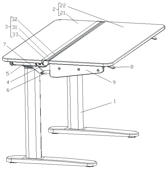
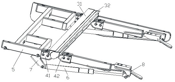
[0048] like figure 1 As shown, a table that can be turned down includes a table leg assembly 1 and a table board assembly 2. The table leg assembly 1 is a lifting table leg, and the table board assembly 2 is composed of a fixed table board 21 and a flip table board 22. The fixed table board 21 is fixed on the table leg assembly 1, the flip table 22 is rotatably connected to one side edge of the fixed table 21, the rotation angle of the flip table 22 is -130°~0°, the difference between the fixed table 21 and the flip table 22 is The connection is provided with a connection component 3 that always covers the connection during the inversion stroke of the inversion table 22. The connection component 3 includes a fixed profile 31 fixed on the fixed table 21 and a flip connected to the inversion table 22 following its action. The profile 32 is always overlapped with the fixed profile 31 during the action of the overturned profile 32 .
[0049] like figure 2 and image 3As shown,...
Embodiment 2
[0056] The difference from the first embodiment is: Figure 9 As shown, both ends of the vertical section 311 of the fixed profile 31 extend in the horizontal direction to form flanges 314 covering the end of the fixed table 21, and the horizontal section 312 is formed by extending the upper flange 314 of the vertical section 311 in the opposite direction. like Figure 10 As shown, both ends of the vertical connection portion 321 of the inversion profile 32 extend horizontally to form connection flanges 325 covering the end of the inversion table 22 .
[0057] The flange 314 and the connecting flange 325 facilitate the connection and installation of the fixed profile 31 and the overturned profile 32, and also ensure that the connection is not worn by external forces.
Embodiment 3
[0059] The difference with the second embodiment is: as Figure 11 As shown, the inner side of the reversing profile 32 is provided with a support member 10 , and the contour of the upper surface of the support member 10 matches the contour of the inner wall of the reversing profile 32 . The inner end of the support member 10 is provided with a barb portion 101 , and the end of the arcuate extension portion 323 is provided with a snap-fit section 3231 matched with the barb portion 101 . Specifically, as Figure 12 As shown, the inner end of the support member 10 is provided with a 7-shaped notch 102, and a reverse 7-shaped barb portion 101 is formed at the bottom of the 7-shaped notch 102, and the barb portion 101 and the notch 102 are formed with a left upper end. In the accommodating part of the opening, the clipping section 3231 is in a stepped structure, which is limited by the opening after entering the accommodating part through the opening.
[0060] The support 10 c...
PUM
 Abstract
Description
Claims
Application Information
 - R&D
- Intellectual Property
- Life Sciences
- Materials
- Tech Scout
- Unparalleled Data Quality
- Higher Quality Content
- 60% Fewer Hallucinations
Browse by: Latest US Patents, China's latest patents, Technical Efficacy Thesaurus, Application Domain, Technology Topic, Popular Technical Reports.
© 2025 PatSnap. All rights reserved.Legal|Privacy policy|Modern Slavery Act Transparency Statement|Sitemap|About US| Contact US: help@patsnap.com


