
Unmanned aerial vehicle with spiral feeding and sowing mechanism

A technology of seeding mechanism and screw feeding, which is applied in the directions of seeder parts, hole seeding machine, seeding, etc., can solve the problems of uncontrollable planting depth, increased manual labor, and no automatic seeding, etc., and achieves increased automatic seeding function. , Increase the survival rate of germination, the effect of accurate planting position

Active Publication Date: 2021-05-14
江苏苏启智能科技有限公司
View PDF10 Cites 0 Cited by
  • Summary
  • Abstract
  • Description
  • Claims
  • Application Information

AI Technical Summary

Problems solved by technology

[0005] Based on the search of the above two patents and the combination of the equipment in the prior art, it was found that the original UAV was not equipped with a seeding mechanism with screw-feeding automatic seeding and automatic seed burying functions when it was used in the agricultural field, so As a result, some remote land cannot be opened with agricultural machinery and equipment, so it is impossible to use mechanical sowing, and only human labor can be used for sowing. Drones do not have the functions of automatic sowing and automatic burying of seeds. Human sowing not only reduces the work efficiency of sowing , and the planting position of the seeds is not accurate enough, resulting in that the planting depth is not adjustable, and can not be adjusted freely according to the actual planting depth of the seeds, and it also makes it impossible for the seeds to be automatically sorted and stripped, and increases human labor. The scientific planting and survival conditions of seeds cannot be guaranteed, which not only reduces the germination and survival rate of seeds, but also reduces the practicability of drones

Method used


Image

  • Unmanned aerial vehicle with spiral feeding and sowing mechanism
  • Unmanned aerial vehicle with spiral feeding and sowing mechanism
  • Unmanned aerial vehicle with spiral feeding and sowing mechanism

Examples


Embodiment

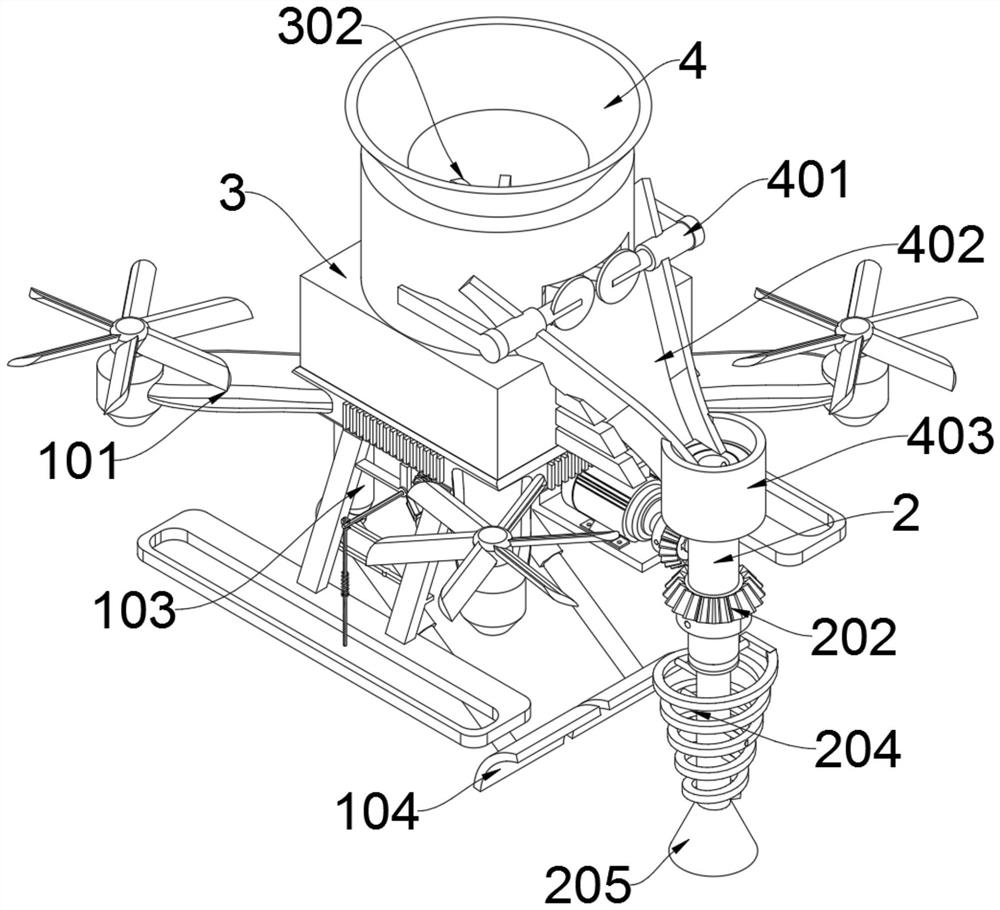
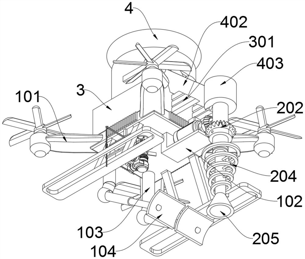
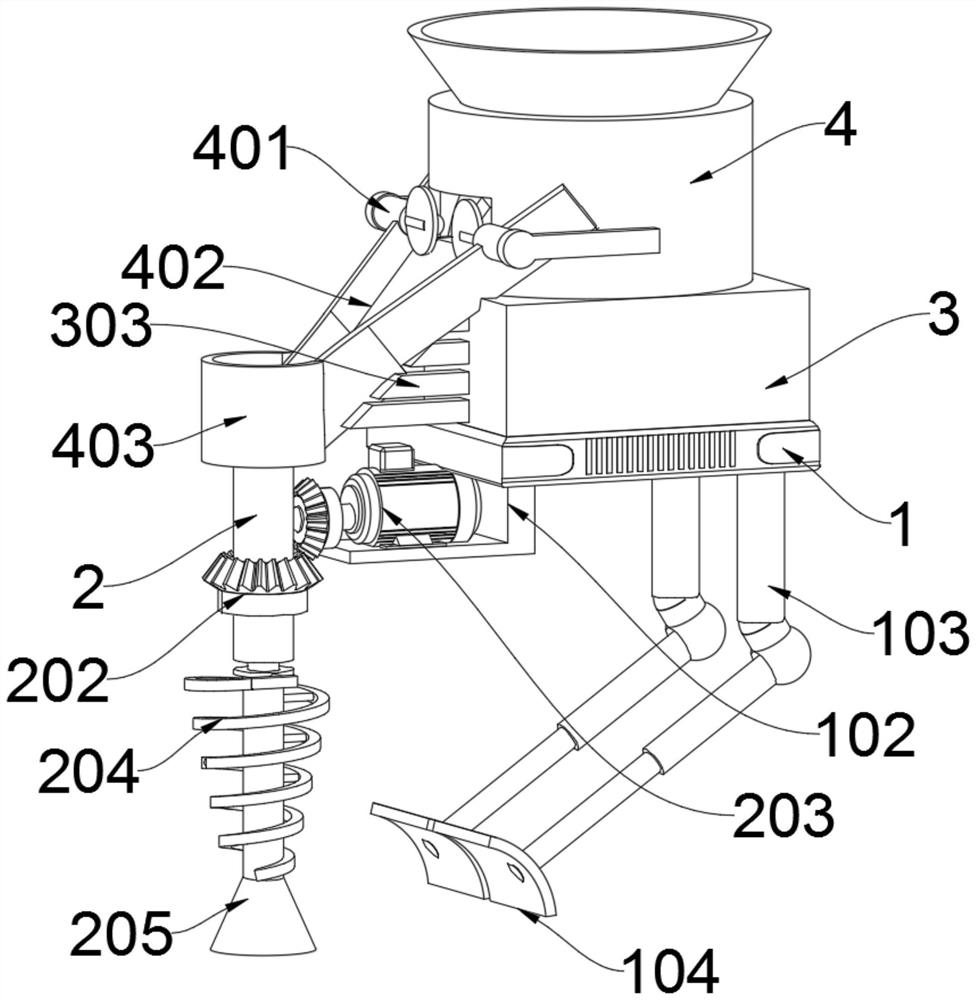
[0033] as attached figure 1 To attach Figure 7 Shown:

[0034] The invention provides an unmanned aerial vehicle with a spiral feeding and seeding mechanism, which includes a base 1; the base 1 is a cuboid structure, and a hollow cylindrical filter tube 2 is vertically fixed on the outer end of the base 1; the base 1 is centered on the upper end The inner cabinet 3 of hollow cuboid shape is connected and installed; the center upper end of inner cabinet 3 is connected and installed with a hollow storage box 4 made up of a cylinder and a cone; A set of wings 101 are respectively installed at the four corners on the outside of the base 1, and an L-shaped stand 102 is fixedly installed on the front side of the lower end of the base 1, and a pair of spherical and cylindrical bodies are respectively connected to the rear of the stand 102. Adjusting rod 103, the top of the front end of adjusting rod 103 is respectively connected and installed with a pair of push plates 104 made of...


PUM


Abstract

The invention provides an unmanned aerial vehicle with a spiral feeding and sowing mechanism, relates to the technical field of unmanned aerial vehicle sowing, and aims to solve the problems that when an original unmanned aerial vehicle is daily used in the agricultural field, a sowing mechanism with spiral feeding, automatic sowing and automatic seed burying functions is not installed, so that the sowing working efficiency is reduced, the planting depth is not adjustable, the germination survival rate of seeds is reduced, and meanwhile the practicability of the unmanned aerial vehicle is reduced. The unmanned aerial vehicle comprises a base, wherein the base is of a cuboid structure, and a hollow cylindrical filter pipe is vertically and fixedly installed at the outer end of the right front of the base. Due to the fact that the a push plate is additionally arranged to move repeatedly along the adjusting rod, the automatic sowing function of the feeding and sowing mechanism is added; and the push plate can horizontally and flatly push sown ground soil grooves, so that the automatic seed burying function is added, and all manual labor force is effectively replaced.

Description

technical field [0001] The present invention relates to the technical field of unmanned aerial vehicle sowing, and more specifically relates to an unmanned aerial vehicle with a screw feeding sowing mechanism. Background technique [0002] Unmanned aircraft, referred to as "unmanned aerial vehicle", is an unmanned aircraft controlled by radio remote control equipment and self-contained program control device, or is completely or intermittently operated autonomously by the on-board computer. According to the application field of the drone, It can be divided into military use and civilian use. At present, it is widely used in aerial photography, agriculture, plant protection and other fields in civilian use. One of the drones with a screw feeding and seeding mechanism is showing the unique advantages of drones in the agricultural field. And Developed countries are also actively expanding industry applications and developing drone technology. [0003] For example, the patent N...

Claims


Application Information

Patent Timeline
Patent Type & Authority Applications(China)
IPC IPC(8): B64D1/16B64D47/00A01C7/20A01C7/00A01C5/04
CPCB64D1/16B64D47/00A01C7/20A01C7/002A01C5/04Y02P60/20
Inventor 傅荣
Owner 江苏苏启智能科技有限公司
Learn More