Vibrating conveyor
A vibrating conveyor and motion technology, applied in the directions of vibrating conveyors, conveyors, transportation and packaging, can solve the problems of increasing cost and installation space, generating control loads, etc., and achieve the goal of suppressing the increase in cost and installation space. Effect
- Summary
- Abstract
- Description
- Claims
- Application Information
AI Technical Summary
Problems solved by technology
Method used
Image

Examples
no. 1 Embodiment approach >
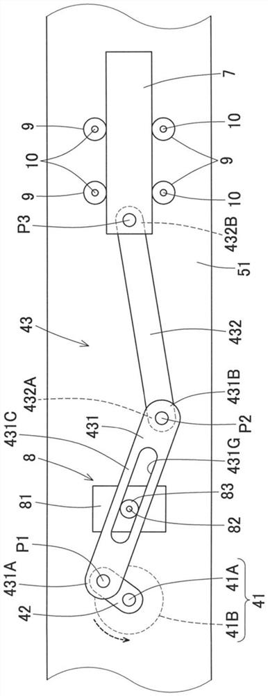
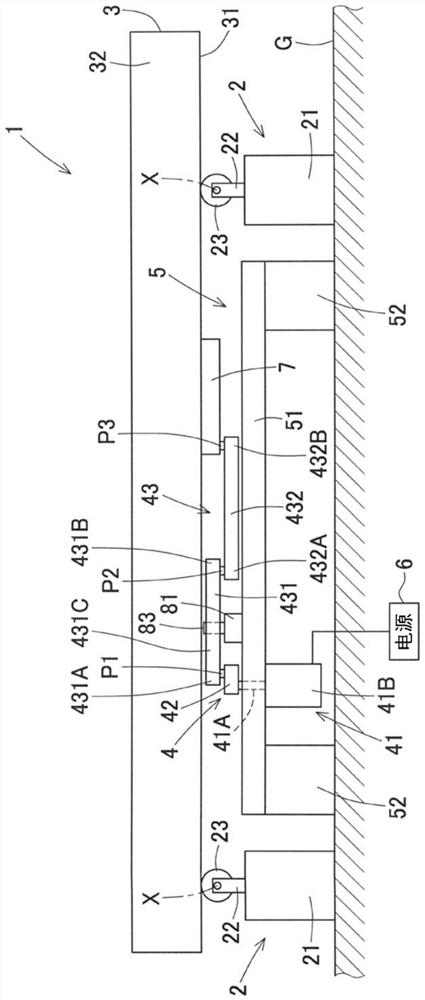
[0033] exist figure 2 In the figure, the vibrating conveyor 1 of the first embodiment of the present embodiment is shown. In addition, in figure 2 In the drawings, the left-right direction (longitudinal direction) in the drawing is referred to as the front-rear direction, and the direction passing through the paper surface is referred to as the left-right direction, which will be described below. The vibration conveyor 1 includes: a groove 3 supported on the ground G via a support portion 2 and capable of reciprocating in the front-rear direction; and a driving portion 4 for reciprocating the groove 3 .
[0034] exist figure 2 In the above, the support portion 2 supports the front and rear end portions of the groove 3, but the support portion 2 is also provided at the left and right end portions, and the groove 3 is supported at four places in total. Each supporting part 2 includes: a fixed block 21 fixed to the ground G; surface.
[0035] The groove 3 is formed long i...
no. 2 Embodiment approach >
[0053] In the first embodiment, the plate member 51 supporting the driving unit 4 is configured to be fixed to the leg portion 52 provided on the ground G so that the reaction force when the vibrating conveyor 1 is driven is transmitted to the ground. simple structure. On the other hand, in 2nd Embodiment, the reaction force at the time of driving the vibrating conveyor 1 is hard to be transmitted to the ground. Specifically, it can also be, such as Figure 5 As shown, it is constituted by a plurality of (specifically, four pieces arranged at the four corners of the plate member 51 ) support bodies 18 abutting against the support plate member 51 from below. Each supporting body 18 includes: a fixed block 181, which is fixed to the ground G; and a wheel 183, which is rotatably mounted on a support member 182 extending above the fixed block 181 around the horizontal axis X1, and abuts against the bottom of the support groove 3. surface. In addition, a balance weight 19 is att...
no. 3 Embodiment approach >
[0056] can also be, eg Figure 6As shown, the vibration conveyor 1 shown in the second embodiment is provided with a spring (here, a coil spring, but a coil spring, a leaf spring, etc.) 20 which is an elastic body, and implemented. Specifically, the rear end of the fixed block 21 on the front side fixed to the ground G and the front end of the plate member 51 are connected by a spring (coil spring) 20 along the front-rear direction (horizontal direction), and The spring (coil spring) 20 (horizontal direction) connects the front end of the fixing block 21 positioned on the rear side fixed to the ground G and the rear end of the plate member 51 . By arranging the spring 20 in this way, the plate member 51 has a restoring force toward a predetermined center position, and when the vibrating conveyor 1 is driven, the plate member 51 and the groove 3 reciprocate around the predetermined position. In addition, the same code|symbol is attached|subjected to the part of the same struct...
PUM
 Abstract
Description
Claims
Application Information