Load reduction method for wind driven generator

A wind power generator and load reduction technology, which is applied to wind power generators, control of wind power generators, wind power generation, etc., can solve problems such as increased production costs, exceeding design loads, and accidents, so as to speed up feathering speed and avoid large loads , Inhibit the effect of speeding

Active Publication Date: 2021-05-14
SHANGHAI ELECTRIC WIND POWER GRP CO LTD
View PDF6 Cites 2 Cited by
  • Summary
  • Abstract
  • Description
  • Claims
  • Application Information

AI Technical Summary

Problems solved by technology

However, after feathering, the sharp change of wind direction may lead to a larger windward area of ​​the wind turbine, causing the wind turbine to bear a larger load. At this time, the hub M YN The directional load is likely to exceed the design load, resulting in an accident
In order to meet the load requirements, it is necessary to increase the model of the hub or replace other parts with better quality, resulting in an increase in production costs. In the current era of wind turbine parity, this is obviously very unfavorable for wind turbine manufacturers.

Method used


Image

  • Load reduction method for wind driven generator
  • Load reduction method for wind driven generator
  • Load reduction method for wind driven generator

Examples


Embodiment Construction

[0023] based on the following figure 2 and image 3 , specifically explain the preferred embodiment of the present invention.

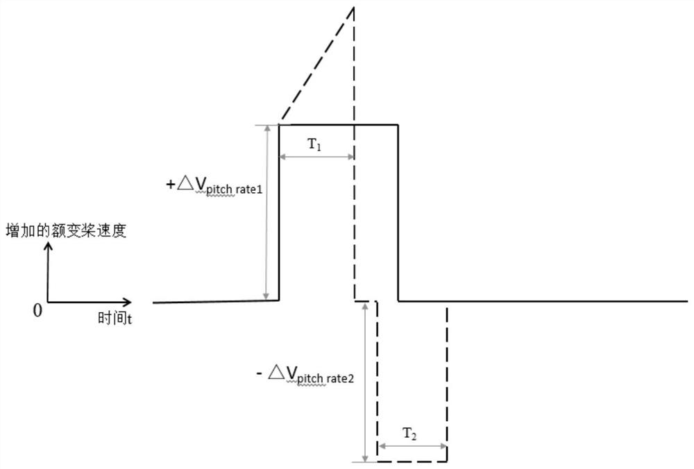
[0024] The present invention provides a wind power generator load reduction method, which monitors the first speed factor and the second speed factor in real time, and when the first speed factor exceeds a threshold and the second speed factor is greater than 0, an additional positive variable is added to the wind power generator. Propeller speed, after adding a positive additional pitch speed to the wind generator, when the second speed factor becomes less than 0, then add a negative additional pitch speed to the wind generator.

[0025] The first speed factor S1=V gen ×V gen ’, where V gen is the wind turbine speed, V gen ’ is the derivative of the wind turbine speed.

[0026] The second speed factor S2=(V gen ×V gen ’)’, where V gen is the wind turbine speed, V gen ’ is the derivative of wind turbine speed (ie, angular acceleration). Th...


PUM


Abstract

The invention discloses a load reduction method for a wind driven generator. When a first speed factor exceeds a threshold value and a second speed factor is larger than 0, a positive extra variable pitch speed is added to the wind driven generator, and after the positive extra variable pitch speed is added to the wind driven generator, and when the second speed factor becomes smaller than 0, a negative extra variable pitch speed is added to the wind driven generator. The overspeed of the generator is restrained under the extreme wind speed, the feathering speed of a unit is increased, a propeller is collected in time after the feathering speed is increased, and the large load is avoided.

Description

technical field [0001] The invention relates to a load reduction method for a wind power generator. Background technique [0002] With the continuous advancement of wind turbine technology, the length of blades is also increasing. In the design stage of wind turbines, it is found that large loads often occur under the conditions of sharply increased wind speed and sharply changed wind direction, which is mainly reflected in the hub coordinate system. m YN direction. Wind turbines have several different coordinate systems, the hub coordinate system, the blade root coordinate system, and the tower coordinate system. Taking the hub center as the zero point, the stationary hub coordinate system is as follows: figure 1 As shown, M stands for torque, F stands for force, N stands for norotaing, non-rotating, that is, static direction. For steady-state calculations, the wind is considered to be blowing from the north, and the origin is at the center of the hub (the intersection ...

Claims


Application Information

Patent Timeline
Patent Type & Authority Applications(China)
IPC IPC(8): F03D7/02F03D7/04
CPCF03D7/0224F03D7/0276F03D7/042Y02E10/72
Inventor 屈云岚黄雄哲顾爽安少朋
Owner SHANGHAI ELECTRIC WIND POWER GRP CO LTD
Why Eureka
Try Eureka