
Construction vehicle

a construction vehicle and engine technology, applied in the direction of servomotors, mechanical vibration separation, ways, etc., to achieve the effect of reducing the overspeed of the engine and simple configuration

Active Publication Date: 2022-11-08
SAKAI HEAVY INDS
View PDF9 Cites 0 Cited by
  • Summary
  • Abstract
  • Description
  • Claims
  • Application Information

AI Technical Summary

Benefits of technology

[0017]The construction vehicle of the present invention suppresses overspeed of the engine with a simple configuration.

Problems solved by technology

Accordingly, there is a risk that rotation speed of an engine is excessively increased.
Overspeed more than allowable rotation speed of the engine may cause valve surging, resulting in that valves, rocker arms, or the like may be damaged, and the vehicle cannot be operated.
Further, damage to the engine at that time is severe, and repair costs are also high.
However, there is a limit to rely on human operations because the operator may forget a switching operation when the vehicle rolls on a downhill at the time of being deadheaded.
If the vehicle speed transmitter is automatically switched to the low speed, a discharge amount of hydraulic oil is switched during high rotation speed, which applies a high load to a rolling-use motor, to have the rolling-use motor itself likely damaged.
Automatically applying braking means sudden braking unanticipated for the operator to presumably give an overload to the operator.
However, it is unpractical to mount an engine, having a larger displacement than required, for engine brake power.
In recent circumstances where exhaust gas regulations are strict, it is not possible to easily modify a configuration.
However, from a viewpoint of a mounting location or costs, it is difficult to adapt additional braking, except a case where the adaptation is sufficiently considered since an initial stage of development.

Method used


Image

  • Construction vehicle
  • Construction vehicle
  • Construction vehicle

Examples


example

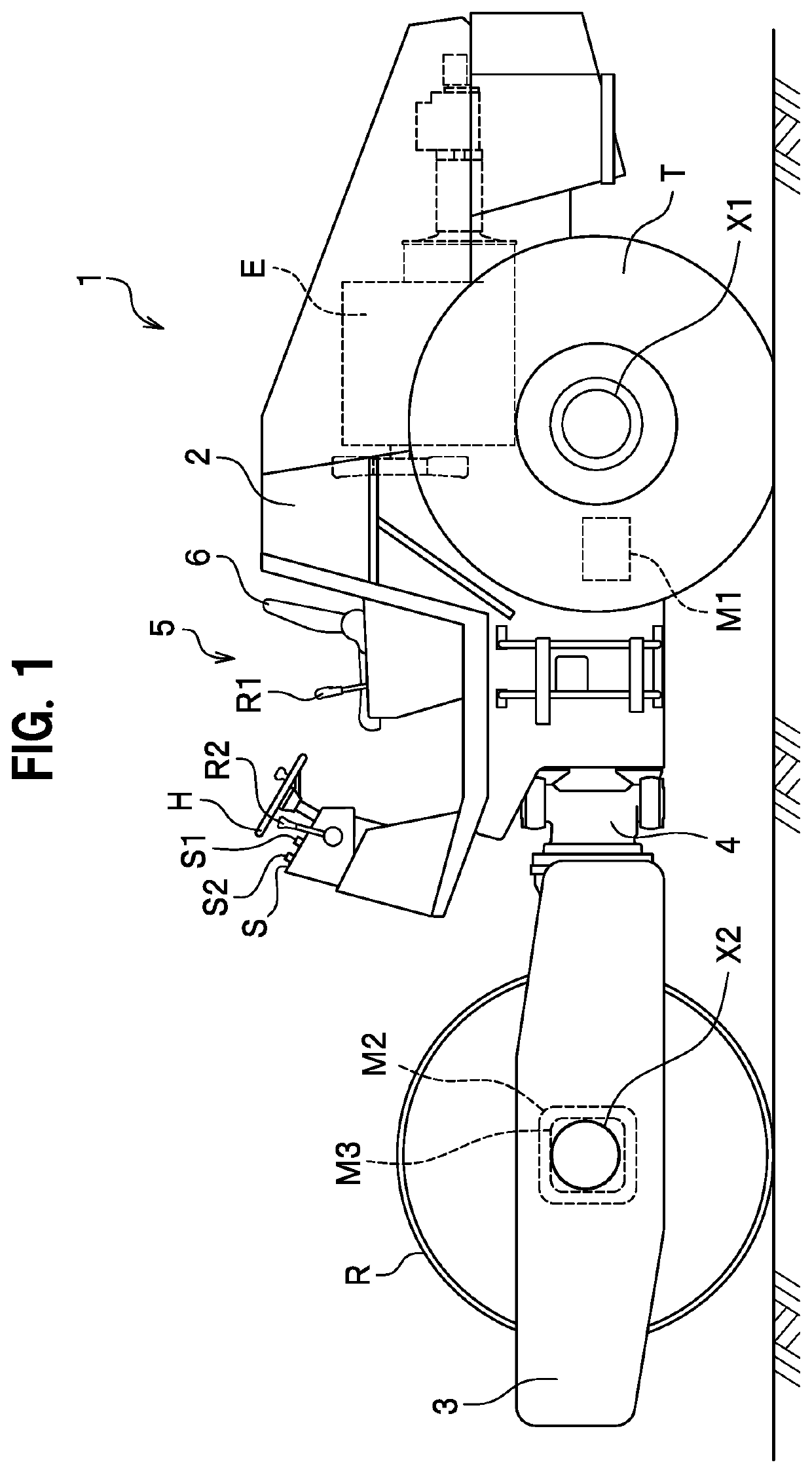
[0062]Next, a description will be given of a usage example of the present invention. An overrun test was made with the vibrating roller 1. In the overrun test, a vibrating roller (SAKAI HEAVY INDUSTRIES, LTD. SV513) was used. In the overrun test, a vibrating roller without the overspeed suppression mechanism 30 (comparative example) and the vibrating roller 1 with the overspeed suppression mechanism 30 (usage example) were rolled on the same downhill, to measure oil pressure of the rolling-use hydraulic pump, oil pressure of the vibration-use hydraulic pump, and rotation speed of the engine, and to confirm an effect of suppressing the rotation speed of the engine. The vibrating roller 1 rolled with the throttle lever R2 in full throttle. The speed of the vibrating roller 1 with the throttle lever R2 in full throttle was about 10 km / h on a flat ground.

[0063]FIG. 6 is a graph showing oil pressure of the rolling-use hydraulic pump, oil pressure of the vibration-use hydraulic pump, and ...


PUM


Abstract

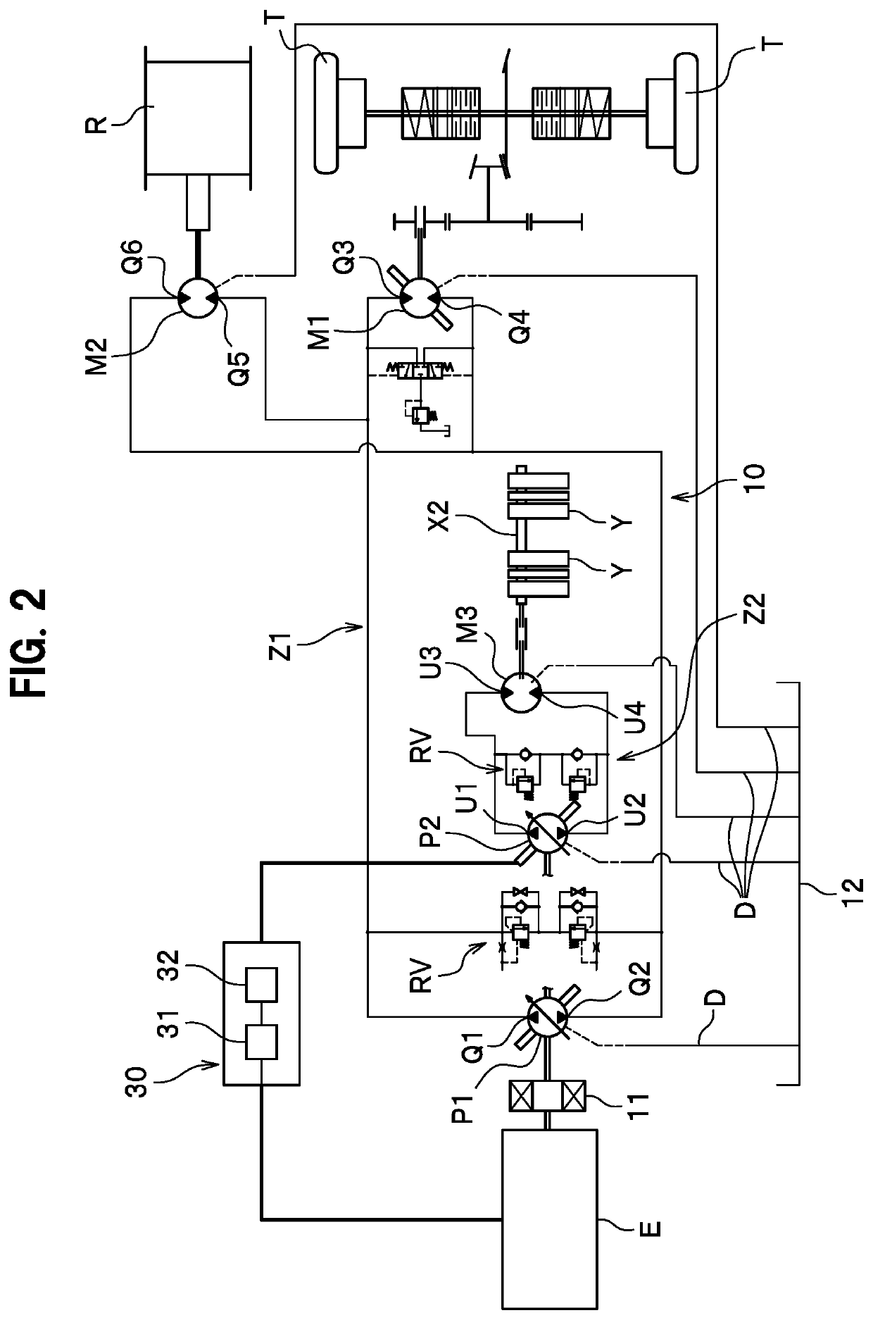
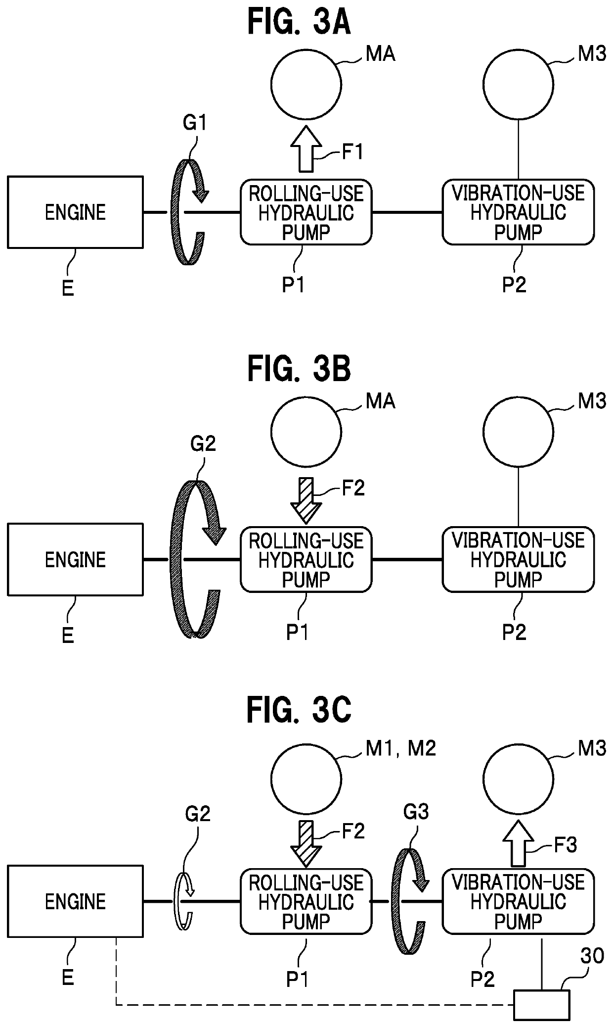
Provided is a construction vehicle including: a rolling-use hydraulic pump coupled to an output shaft of an engine and supplying hydraulic oil to a rolling-use hydraulic circuit; a task-use hydraulic pump coupled to the output shaft of the engine and supplying the hydraulic oil to a task-use hydraulic circuit; and an overspeed suppression mechanism configured to activate the task-use hydraulic pump to suppress overspeed of the engine when a load equal to or greater than allowable rotation speed is applied from the rolling-use hydraulic pump to the output shaft of the engine.

Description

CROSS-REFERENCE TO RELATED APPLICATIONS[0001]This application is a § 371 national phase entry of International Application No. PCT / JP2018 / 045618, filed Dec. 12, 2018, which claims priority to Japanese Patent Application No. 2018007195, filed Jan. 19, 2018.TECHNICAL FIELD[0002]The present invention relates to a construction vehicle.BACKGROUND ART[0003]Patent Literature 1 discloses a construction vehicle to roll and stop with use of a hydro Static transmission (HST).CITATION LISTPatent Literature[0004]Patent Literature 1: Japanese Patent Application Publication No. 2005-279363SUMMARY OF THE INVENTIONProblems to be Solved[0005]When the construction vehicle rolls on a downhill when being deadheaded or the like or is stopped (returning a forward-backward lever to the neutral position) with use of the HST on a downhill, fall energy of the vehicle may be greater than engine brake power. Accordingly, there is a risk that rotation speed of an engine is excessively increased. Overspeed more t...

Claims


Application Information

Patent Timeline
Patent Type & Authority Patents(United States)
IPC IPC(8): E01C19/28B06B1/16F02B63/00F02D31/00F15B11/00
CPCE01C19/286B06B1/16F02B63/00F02D31/001F15B11/00E01C19/28F02D41/0205F02D2200/702F02D2250/24F02D2200/101F15B7/003F15B11/17F15B2211/20523F15B2211/7058F15B2211/71F15B2211/761F15B2211/20569F15B2211/20561F15B2211/20576
Inventor ISHIDA, SHINJITOYOSHIMA, KENTA
Owner SAKAI HEAVY INDS
Learn More