
Novel refrigeration plate evaporator and manufacturing method thereof

A manufacturing method and technology for refrigeration panels, which are applied to evaporators/condensers, refrigerators, refrigeration components, etc., can solve the problems of inconvenient production and manufacturing process of refrigeration panels, time-consuming and laborious, and difficulty in rapid refrigeration of blood plasma bags.

Pending Publication Date: 2021-05-14
深圳市爱康生物科技股份有限公司
View PDF0 Cites 0 Cited by
  • Summary
  • Abstract
  • Description
  • Claims
  • Application Information

AI Technical Summary

Problems solved by technology

The deficiencies in the refrigerating plate of the plasma quick-freezing equipment in the prior art have the following aspects: (1) heat exchange tubes are arranged in the refrigerating plate, and the bends of the heat exchange tubes are connected with straight pipes and elbows by welding technology. There are two welding joints at each elbow, and dozens of welding joints will be formed on one refrigeration plate, which will bring great inconvenience to the manufacturing process of the refrigeration plate; (2) the inner pipe wall of the welding place will have weld (3) Limited by the manufacturing process, the heat exchange tubes are not tightly arranged, which makes it difficult for the blood plasma bags on the refrigeration plate to achieve simultaneous and uniform rapid cooling, thus affecting The quick-freezing effect of the plasma bag; (4) The groove for placing the heat exchange tube needs to be dug out in the refrigeration plate, which is time-consuming and laborious in mass production, and there is a gap between the refrigeration plate and the heat exchange tube, which affects the cooling effect

Method used


Image

  • Novel refrigeration plate evaporator and manufacturing method thereof
  • Novel refrigeration plate evaporator and manufacturing method thereof
  • Novel refrigeration plate evaporator and manufacturing method thereof

Examples


Embodiment Construction

[0029] In order to make the object, technical solution and advantages of the present invention clearer, the implementation manners of the present invention will be further described below in conjunction with the accompanying drawings. Apparently, the described embodiments are only some of the embodiments of the present invention, but not all of them. Based on the embodiments of the present invention, all other embodiments obtained by persons of ordinary skill in the art without making creative efforts belong to the protection scope of the present invention.

[0030] It should be noted that all directional indications (such as up, down, left, right, front, back, etc.) When the specific posture changes, the directional indication also changes accordingly.

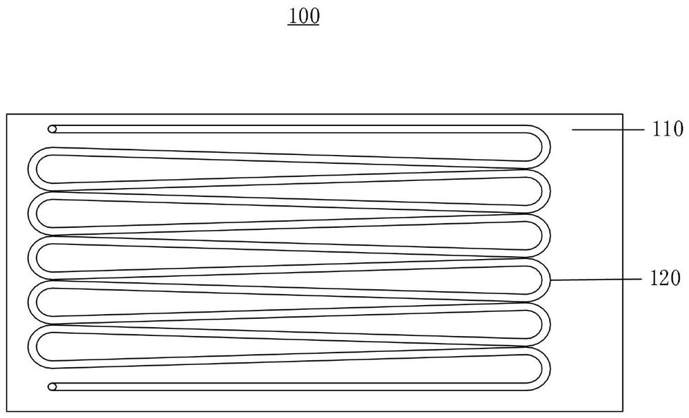
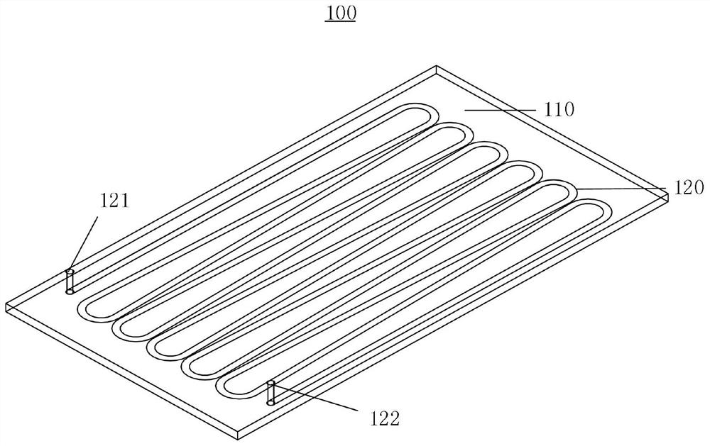
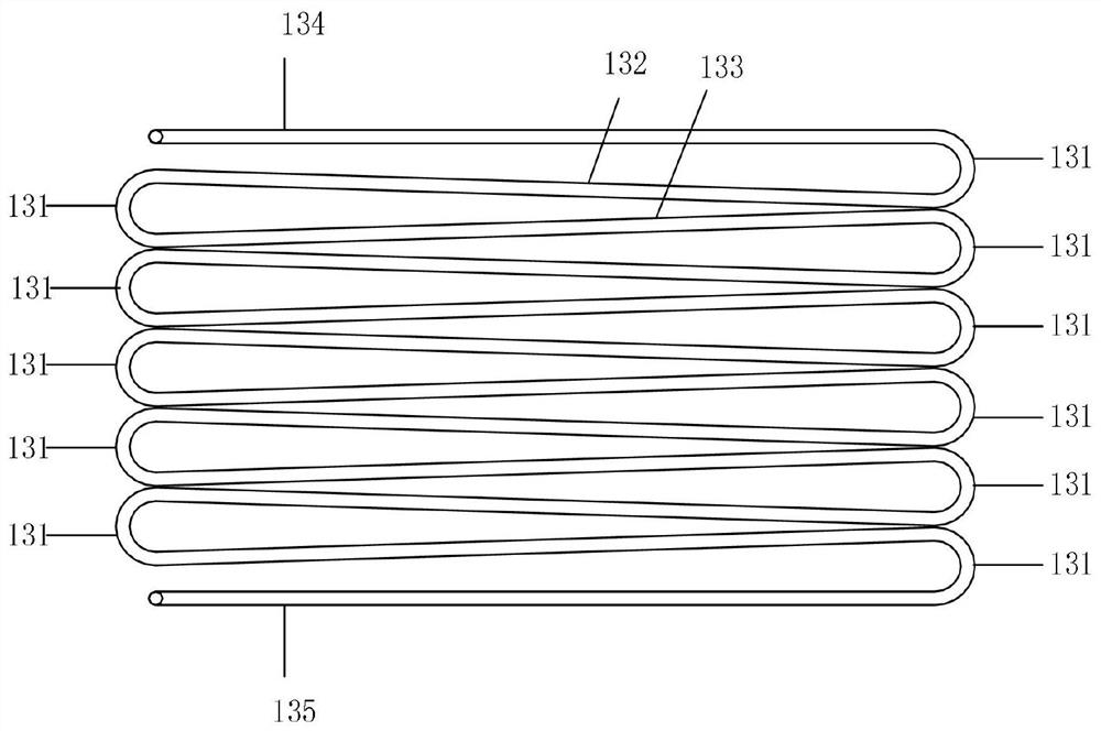
[0031] Such as Figure 1-4 As shown, a novel refrigerating plate evaporator 100 includes a refrigerating plate 110 and a coil 120. The coil 120 is arranged in the refrigerating plate 110. The two ends of the coil 120 are re...


PUM

PropertyMeasurementUnit
radiusaaaaaaaaaa

Abstract

A novel refrigeration plate evaporator comprises a refrigeration plate and a coil pipe, the coil pipe is arranged in the refrigeration plate, two ends of the coil pipe are correspondingly connected with an inlet pipe and an outlet pipe, the coil pipe is formed by bending a straight pipe multiple times, the coil pipe comprises a plurality of bent pipes, the bent pipes comprise arc pipes, first-direction inclined pipes and second-direction inclined pipes, one ends of the arc pipes are connected with the first-direction inclined pipes, the other ends of the arc pipes are connected with the second-direction inclined pipes, the first-direction inclined pipes and the second-direction inclined pipes are in mirror symmetry with horizontal center lines of the arc pipes between the first-direction inclined pipes and the second-direction inclined pipes as an axis, the arc pipes are located at the left end and the right end of the refrigeration plate, and the arc pipes are tightly arranged. According to the novel refrigeration plate evaporator, the welding process is avoided, the coil pipe forms the closely-arranged bent pipes in a natural bending mode, the quick-freezing effect of the refrigeration plate is better, the coil pipe and the refrigeration plate form a whole through the casting process, the manufacturing process is simplified, and the cold conduction effect of the refrigeration plate is better.

Description

technical field [0001] The invention relates to the field of plasma quick-freezing equipment, in particular to a novel refrigeration plate evaporator and a manufacturing method thereof. Background technique [0002] Plasma quick-freezing equipment is usually a flat contact quick-freezer. During use, the plasma bag is placed flat on the refrigeration plate, and the plasma bag is directly in contact with the refrigeration plate for heat transfer, so that the plasma bag can be cooled rapidly. The deficiencies in the refrigerating plate of the plasma quick-freezing equipment in the prior art have the following aspects: (1) heat exchange tubes are arranged in the refrigerating plate, and the bends of the heat exchange tubes are connected with straight pipes and elbows by welding technology. There are two welding joints at each elbow, and dozens of welding joints will be formed on one refrigeration plate, which will bring great inconvenience to the manufacturing process of the ref...

Claims


Application Information

Patent Timeline
Patent Type & Authority Applications(China)
IPC IPC(8): F25B39/02F28F21/08B21D7/00B22D35/04B24B1/00
CPCB21D7/00B22D35/04B24B1/00F25B39/02F28F21/084F28F21/085
Inventor 江胜标刘天睿李运奇
Owner 深圳市爱康生物科技股份有限公司
Learn More