
Vehicle motor controller harmonic current detection system and method

A motor controller and harmonic current technology, applied in the direction of only measuring current, measuring current/voltage, instruments, etc., can solve problems such as poor dynamic response performance, improve response speed, reduce phase lag, and reduce fluctuations Effect

Pending Publication Date: 2021-05-14
UNITED AUTOMOTIVE ELECTRONICS SYST
View PDF8 Cites 0 Cited by
  • Summary
  • Abstract
  • Description
  • Claims
  • Application Information

AI Technical Summary

Problems solved by technology

[0005] The purpose of the present invention is to provide a vehicle motor controller harmonic current detection system and method to solve the problem of poor dynamic response performance caused by the existing harmonic current extraction

Method used


Image

  • Vehicle motor controller harmonic current detection system and method
  • Vehicle motor controller harmonic current detection system and method
  • Vehicle motor controller harmonic current detection system and method

Examples


Embodiment 1

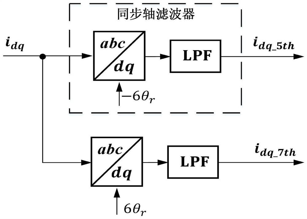
[0042] The present invention provides a vehicle motor controller harmonic current detection system. The vehicle motor controller harmonic current detection system includes a front-end coordinate transformation unit, a current harmonic residual unit and a filter unit, wherein: the front-end coordinate transformation The unit is used to transform the coordinates of the three-phase current input by the vehicle motor to obtain the sum of the d-q axis fundamental current and each harmonic current; In the sum of harmonic currents, it is used to remove the harmonic currents of the d-q axis, leaving the fundamental current of the d-q axis, or removing the fundamental current of the d-q axis and other harmonic currents of the d-q axis except for a certain harmonic current of the d-q axis, leaving the remaining A certain harmonic current of the d-q axis obtains the 1st, 2nd, ..., N residual currents, where N is a positive integer; the filtering unit is used to filter the 1st, 2nd, ..., N...

Embodiment 2

[0056]The present invention also provides a method for detecting the harmonic current of the vehicle motor controller. The method for detecting the harmonic current of the vehicle motor controller includes: the front-end coordinate transformation unit performs coordinate transformation on the three-phase current input by the vehicle motor to obtain the d-q axis The sum of the fundamental current and each harmonic current; the current harmonic residual unit removes each harmonic current of the d-q axis from the sum of the d-q axis fundamental current and each harmonic current, and the remaining d-q axis fundamental current , or remove the d-q axis fundamental wave current and d-q axis other harmonic currents except for a certain harmonic current of the d-q axis, and leave the d-q axis certain harmonic current to obtain the 1st, 2nd, ..., Nth residual current, where , N is a positive integer; the filtering unit filters the 1st, 2nd, ..., Nth order residual currents to obtain 1st,...


PUM


Abstract

The invention provides a vehicle motor controller harmonic current detection system and method. The system comprises a front-end coordinate transformation unit, a current harmonic residual unit, and a filtering unit. The front-end coordinate transformation unit is used for carrying out coordinate transformation on three-phase current input by the vehicle motor to obtain the sum of d-q axis fundamental wave current and harmonic current of each time; the current harmonic residual unit is used for removing each harmonic current of the d-q axis or removing the fundamental current of the d-q axis and other harmonic currents of the d-q axis except a certain harmonic current of the d-q axis in the sum of the fundamental current of the d-q axis and each harmonic current; and the filtering unit is used for filtering the first, second,..., Nth residual current. On one hand, phase lag introduced in the filtering process of other harmonic components by the low-pass filter is reduced, the response speed of harmonic current extraction is improved, on the other hand, the attenuation coefficient of other harmonic components by the low-pass filter is increased, and the fluctuation quantity of the extracted harmonic current is reduced.

Description

technical field [0001] The invention relates to the technical field of vehicle motors, in particular to a system and method for detecting harmonic currents of vehicle motor controllers. Background technique [0002] Due to reasons such as cogging, non-sinusoidal air-gap magnetic field, and harmonic currents, torque ripple commonly exists in automotive motors, which can cause torsional vibrations in traditional vehicle systems at low speeds, and cause howling inside the vehicle at medium and high speeds. , as shown in Figure 1(a) and Figure 1(b), thereby reducing the ride comfort of the vehicle. Active harmonic current injection can effectively suppress the motor torque ripple, from figure 2 It can be seen that the torque ripple can be greatly reduced by injecting a small amount of harmonic current. This method is completely based on software optimization and can be implemented on the original electric drive system hardware platform without adding additional costs; and for ...

Claims


Application Information

Patent Timeline
Patent Type & Authority Applications(China)
IPC IPC(8): G01R19/00G01R23/16
CPCG01R19/0092G01R23/16
Inventor 江尚马艳丽周英坤
Owner UNITED AUTOMOTIVE ELECTRONICS SYST
Learn More