High-precision micro-displacement actuator for astronomical telescope mirror surface position adjustment

An astronomical telescope, high-precision technology, applied in instruments, installation, optics, etc., can solve the problems of limited travel magnification, immature technology and high price

Pending Publication Date: 2021-05-14
NANJING INST OF ASTRONOMICAL OPTICS & TECH NAT ASTRONOMICAL OBSE
View PDF5 Cites 1 Cited by
  • Summary
  • Abstract
  • Description
  • Claims
  • Application Information

AI Technical Summary

Problems solved by technology

[0004] Due to the complex structure of the coarse and fine combined platform type displacement actuator, the inchworm motor designed by the piezoelectric material using the "inchworm principle" has a large stroke and high precision. High, and can be self-locking when power is off, but the current market price is relatively high, and the domestic technology of this type of product is not yet mature, and for the micro-displacement actuator mechanism that uses the displacement amplification mechanism to amplify the stroke of the piezoelectric material, usually Under normal circumstances, the maximum expansion and contraction of the piezoelectric material per 1 millimeter of length is about 1 micron. Therefore, in order to improve the stroke range of the piezoelectric displacement actuator, although the displacement amplification mechanism is used, the stroke amplification capability is very limited, and at the same time Piezoelectric materials need to be continuously powered
However, for the commonly used reducer plus precision screw structure to achieve micro-displacement output, there is a gap in the transmission of gears or worm gears, and it is inevitable that there will be a gap in the displacement output, which limits its final displacement output accuracy.

Method used


Image

  • High-precision micro-displacement actuator for astronomical telescope mirror surface position adjustment

Examples


Embodiment 1

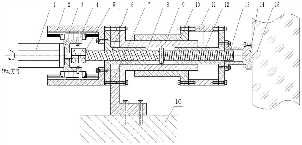
[0023] Such as figure 1 As shown, in this embodiment, a high-precision micro-displacement actuator for adjusting the mirror position of an astronomical telescope includes a double-thread screw 8, and the double-thread screw 8 includes two thread segments with the same helical direction and different leads. That is, the first thread segment (lead P1) and the second thread segment (lead P2), use the relative lead difference between the first thread segment and the second thread segment to realize the displacement output. The outer fitting sleeve of the first threaded section is provided with the first screw nut 6 that is fixedly connected on the telescope frame 16, the first threaded section is connected with a driving device that can drive the rotation of the double threaded screw mandrel 8, and the outer fitting sleeve of the second threaded section A second screw nut 12 is provided, and the second screw nut 12 is connected with the mirror surface 15 . This high-precision mic...


PUM


Abstract

The invention discloses a high-precision micro-displacement actuator for astronomical telescope mirror surface position adjustment. The actuator comprises a double-thread screw rod, the double-thread screw rod comprises two thread sections with the same spiral direction and different leads, namely a first thread section and a second thread section, displacement output is achieved through the relative lead difference of the first threaded section and the second threaded section, the first threaded section is sleeved with a first lead screw nut fixedly connected to the telescope rack in a matched mode, the first threaded section is connected with a driving device capable of driving the double-thread lead screw to rotate, the second threaded section is sleeved with a second lead screw nut in a matched mode, and the second screw rod nut is connected with the mirror surface. According to the high-precision micro-displacement actuator, when the position of the optical mirror surface is adjusted, the mirror surface is continuously displaced, and a gap or backlash phenomenon does not occur. The position adjustment precision of the mirror surface can reach a submicron level or even a nanometer level. Meanwhile, the micro-displacement actuator can be applied to other fields, such as occasions where the position requirement is high when structural parts are installed.

Description

technical field [0001] The invention relates to a precise mirror position adjustment device, in particular to a high-precision micro-displacement actuator. It is mainly used in the position adjustment of the optical mirror of the astronomical telescope. Background technique [0002] In order to reduce the cost and obtain good image quality, large-scale astronomical telescopes mostly use splicing mirror active optical technology, applying modern sensing and control technology, and splicing small-scale sub-mirrors into large-caliber mirrors. The micro-displacement actuator is a precise displacement output device, which completes the positioning, support and adjustment of the sub-mirror in the splicing mirror active optical technology. It must have high resolution, high stability, high stiffness, and high repeatability , large load performance, and millimeter-level travel, while overcoming or reducing harmful defects such as crawling, friction, hysteresis, backlash, and heat g...

Claims


Application Information

Patent Timeline
Patent Type & Authority Applications(China)
IPC IPC(8): G02B7/185
CPCG02B7/185
Inventor 牛冬生
Owner NANJING INST OF ASTRONOMICAL OPTICS & TECH NAT ASTRONOMICAL OBSE
Why Eureka
Try Eureka