Machine room network intelligent supervision method and system

A network intelligence and monitoring system technology, applied in transmission systems, digital transmission systems, data exchange networks, etc., can solve problems such as the inability to meet the operation and maintenance requirements of large-scale computer rooms, the large number of monitoring nodes, and the complexity.

Pending Publication Date: 2021-05-14
豪越科技有限公司
View PDF5 Cites 2 Cited by
  • Summary
  • Abstract
  • Description
  • Claims
  • Application Information

AI Technical Summary

Problems solved by technology

[0002] The 21st century is an era of explosive growth of digital systems, information systems, Internet, and Internet of Things systems. The operation of these systems generally relies on a centralized computer room environment. With the explosive growth of new systems, the computer room environment is also growing in scale. Larger and more complex, the operation and maintenance of the computer room is also facing many challenges
Existing open source monitoring tools can no longer meet the complex operation and maintenance requirements of large-scale computer rooms. Some problems that existing open source tools cannot solve are listed below:
[0003] 1. There are a large number of monitoring nodes, the workload of manual addition is heavy, and it is prone to errors. When the attributes of nodes change, it is difficult for manual detection and follow-up maintenance
[0004] 2. The network topology is complex, and as a monitoring system, it is necessary to display the topology graphically intuitively
[0005] 3. The monitoring points and monitoring types are changeable, and the open source platform is not convenient for special customization of monitoring requirements
[0007] 5. Lack of some early warning mechanisms to assist operation and maintenance staff to discover some hidden problems
[0008] 6. Lack of a network environment security analysis mechanism to assist operation and maintenance personnel in discovering some network attacks
[0009] 7. Lack of automatic fault handling mechanism to assist operation and maintenance staff to promptly and quickly handle node faults

Method used


Image

  • Machine room network intelligent supervision method and system

Examples


Embodiment Construction

[0049] Example embodiments will now be described more fully with reference to the accompanying drawings. Example embodiments may, however, be embodied in many forms and should not be construed as limited to the examples set forth herein; rather, these embodiments are provided so that this disclosure will be thorough and complete and fully convey the concept of example embodiments to those skilled in the art.

[0050] The flow charts shown in the drawings are only exemplary illustrations, and do not necessarily include all contents and operations / steps, nor must they be performed in the order described. Some operations / steps can be decomposed, and some operations / steps can be combined or partly combined, so the actual order of execution may be changed according to the actual situation.

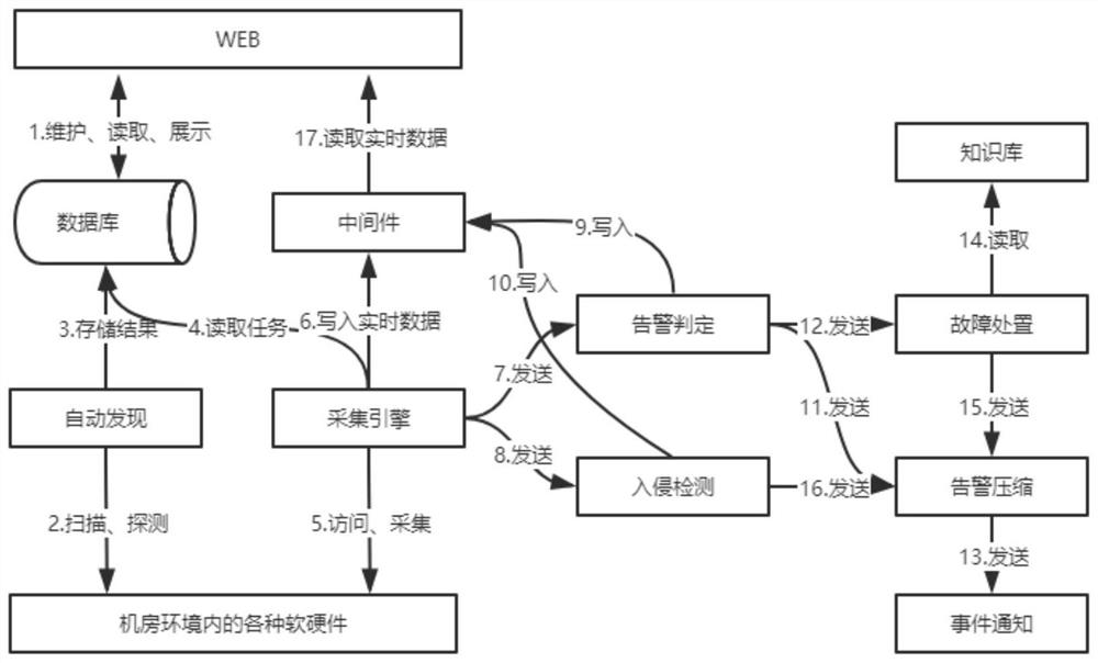
[0051] refer to figure 1 As shown, the system provided by the present invention includes the following sub-modules: human-computer interaction interface, automatic discovery module, acquisiti...


PUM


Abstract

The invention discloses a machine room network intelligent supervision method and system. The method comprises the following steps: S1, adding environment node necessary data; S2, after reading the environment node necessary data stored in the step S1, starting to scan and discover each software and hardware node in an environment range, and forming and storing a discovery result; S3, judging whether a target node needing to be processed exists in the discovery result stored in the step S2 or not, and if yes, executing the step S4, and otherwise, executing the step S2; and S4, carrying out data acquisition on the target node, judging intrusion behavior characteristics of an acquisition result, and if the intrusion behavior characteristics are met, storing an object to which data in the acquisition result belongs, an intrusion event and an intrusion type so as to be read and displayed, and otherwise, storing the collection result for reading and displaying. According to the technical scheme provided by the invention, intrusion monitoring is added, so that the safety of a machine room environment is assisted to be guaranteed to a certain extent.

Description

technical field [0001] The invention belongs to the technical field of computer software programs, and in particular relates to a computer room network intelligent supervision method and system. Background technique [0002] The 21st century is an era of explosive growth of digital systems, information systems, Internet, and Internet of Things systems. The operation of these systems generally relies on a centralized computer room environment. With the explosive growth of new systems, the computer room environment is also growing in scale. Larger and more complex, the operation and maintenance of the computer room is also facing many challenges. Existing open source monitoring tools can no longer meet the complex operation and maintenance requirements of large-scale computer rooms. Some problems that existing open source tools cannot solve are listed below: [0003] 1. There are a large number of monitoring nodes, the workload of manual addition is heavy, and it is prone to ...

Claims


Application Information

Patent Timeline
Patent Type & Authority Applications(China)
IPC IPC(8): H04L29/06H04L12/24
CPCH04L63/1416H04L41/0631
Inventor 汪兆伟
Owner 豪越科技有限公司
Why Eureka
Try Eureka