
vibration device

A technology of vibration device and vibration unit, which is applied in the direction of fluid, instrument, and mechanical mode conversion using vibration, and can solve problems such as hindering the movement of the vibrator.

Active Publication Date: 2022-04-12
MURATA MFG CO LTD
View PDF7 Cites 0 Cited by
  • Summary
  • Abstract
  • Description
  • Claims
  • Application Information

AI Technical Summary

Problems solved by technology

In this case, the sensor receives force in the normal direction, so if it overlaps with the vibrator vibrating in the surface direction, there is a possibility that the movement of the vibrator may be hindered

Method used


Image

  • vibration device
  • vibration device
  • vibration device

Examples


Embodiment Construction

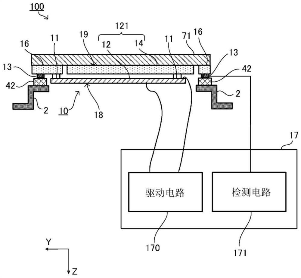
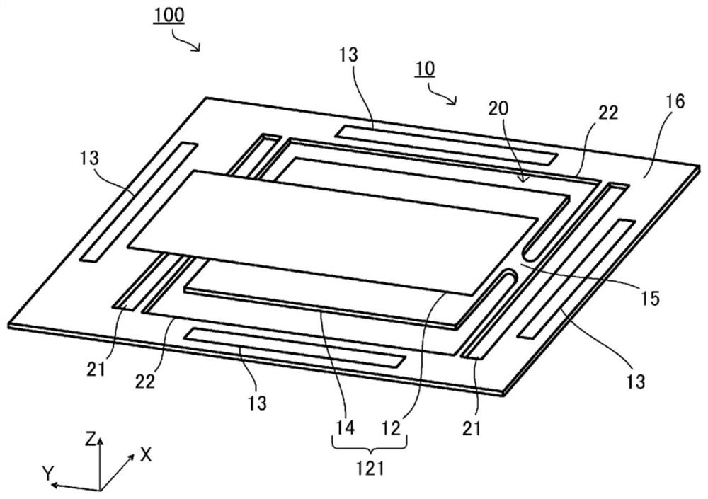
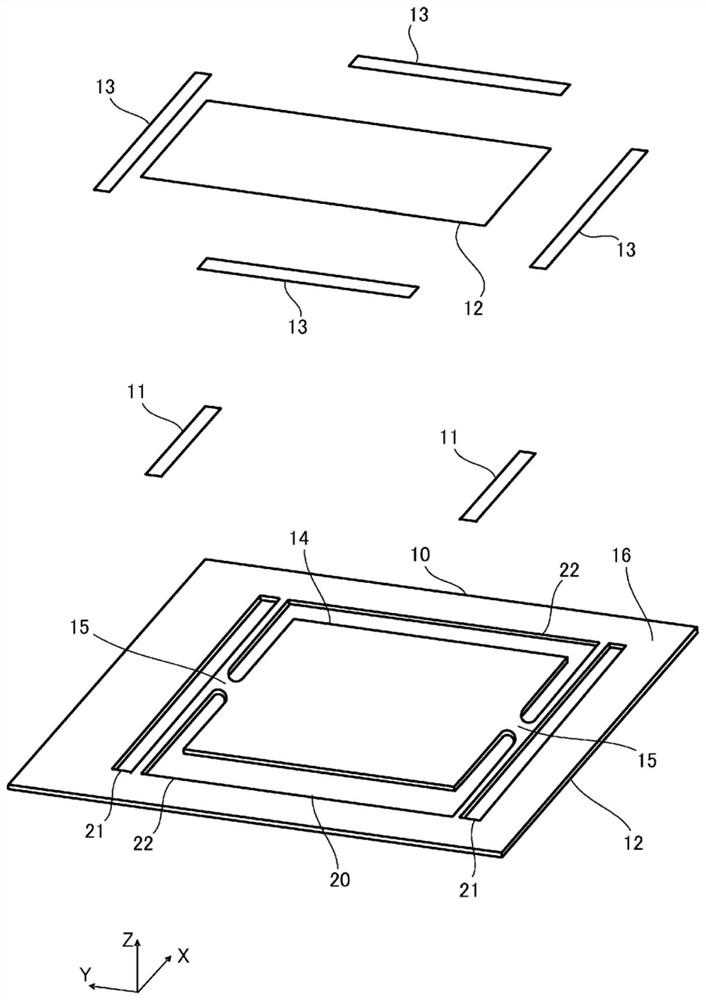
[0023] figure 1 It is a schematic diagram showing the configuration of the vibration device 100 according to the first embodiment. figure 1 A part of the vibration device 100 is shown by a cross-sectional view. figure 2 It is a perspective view showing an example of the vibration device 100 viewed from the back side. image 3 It is an exploded perspective view of the vibration device 100 viewed from the back side. Figure 4 (A) is a plan view of the vibration device 100 viewed from the back side, Figure 4 (B) is in Figure 4 A cross-sectional view taken along line I-I shown in (A). also, Figure 4 (B) shows the state where the vibration device 100 is installed in the case 2 . exist Figure 4 In (A), the housing 2 and the cushioning member 42 are omitted. In addition, except figure 1 In other figures, the circuit 17 and wiring are omitted.

[0024] Such as figure 1 As shown, the vibration device 100 of this embodiment includes a vibration unit 10 , a sensor 13 , a ...


PUM


Abstract

The present invention provides a vibration device capable of detecting deformation in a normal direction without hindering vibration. A vibration unit having a vibrator vibrating in a planar direction; and a sensor disposed at least partly around the vibrator in the vibration unit in plan view and detecting a pressing operation in a normal direction.

Description

technical field [0001] The present invention relates to a vibrating device for generating vibrations. Background technique [0002] In recent years, a tactile feedback device has been proposed that transmits vibration when a user performs a pressing operation in an input device such as a touch panel, thereby allowing the user to actually feel that the user has pressed. [0003] For example, Patent Document 1 proposes a tactile feedback device that uses a film 12 to give tactile feedback to a user. In Patent Document 1, the film 12 is deformed in the plane direction by applying a voltage. The vibrating part 14 connected to the membrane 12 vibrates in the planar direction due to expansion and contraction of the membrane 12 . [0004] Patent Document 1: International Publication No. 2019 / 013164 [0005] When the tactile feedback device has a function of detecting a pressing operation, for example, it is necessary to add a pressing sensor for detecting deformation in the norm...

Claims


Application Information

Patent Timeline
Patent Type & Authority Patents(China)
IPC IPC(8): B06B1/06G06F3/01G06F3/041H03H9/17H10N30/857
CPCH03H9/17G06F3/041B06B1/0688G06F3/03547G06F3/016H10N30/20H10N30/857
Inventor 富永亨木原尚志加纳英和远藤润
Owner MURATA MFG CO LTD
Learn More