Seat floor structure reinforced in case of pole impact

A technology of bottom plate and seat, applied in the direction of substructure, superstructure, subassembly of superstructure, etc., can solve problems such as complex volume of reinforcements

Pending Publication Date: 2021-05-14
PEZHO SITROEN AUTOMOBILS SA
View PDF11 Cites 0 Cited by
  • Summary
  • Abstract
  • Description
  • Claims
  • Application Information

AI Technical Summary

Problems solved by technology

Such prior art stiffeners are complex and bulky

Method used


Image

  • Seat floor structure reinforced in case of pole impact

Examples


Embodiment Construction

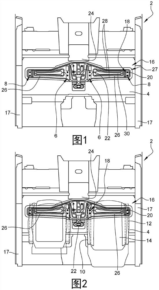
[0023] figure 1 shows a top view of the motor vehicle structure, figure 2 show figure 1 The structure in , which shows a front seat of a motor vehicle. will be described together figure 1 and figure 2 .

[0024] figure 1 and figure 2 A motor vehicle structure 2 comprising a seat pan 4 is shown. The seat pan 4 includes an inner rail 10 and an outer rail 12 ( figure 2 ) fixed area 6, 8 ( figure 1 ). The structure 2 comprises reinforcements 16 arranged transversely on the seat pan 4 . The reinforcement 16 is fastened directly to the seat pan 4 and extends transversely on the front part of said fastening regions 6 , 8 of the inner and outer rails as far as the fastening region 8 of the outer rail 12 of each of the two front seats 14 . The inner rail 10 and the outer rail 12 are fastened to the fastening areas 6 and 8, respectively. The reinforcement 16 is advantageously fixed to said base plate by welding.

[0025] The structure includes two inner underbody rails ...


PUM


Abstract

The invention concerns a motor vehicle structure (2) comprising a seat floor (4) with attachment zones (6, 8) for attaching internal and external rails of each of two front seats; and a reinforcement (16) arranged transversely on the seat floor (4). The reinforcement (16) is attached directly to the seat floor (4) and extends transversely over a front portion of the attachment zones for attaching the internal and external rails (10, 12) up to the attachment zone (8) for attaching the external rail (12) of each of the two front seats. The invention also concerns a motor vehicle comprising such a structure (2).

Description

technical field [0001] The invention relates to the field of motor vehicles, in particular to the structure of motor vehicles. Background technique [0002] Published patent document US2010 / 0295335A1 describes a motor vehicle structure comprising a seat pan and a center pillar or pillars on each side of the vehicle. The structure includes a stiffener in the form of a controllably deformable girder extending transversely across the seat pan. The frame is fastened behind the front seats to the side members of the vehicle structure and to the center pillar of the motor vehicle. The fixed rails for the front seats are fastened to this frame. This reinforcement constricts the vehicle space behind the seats and is not optimal for limiting the rapprochement of the front seats in the event of a choc poteau of the vehicle. [0003] Published patent document EP1671872A1 describes a structure of a motor vehicle comprising a chassis with two lateral longitudinal members forming the s...

Claims


Application Information

Patent Timeline
IPC IPC(8): B62D25/20B62D21/15
CPCB62D21/157B62D25/20
Inventor R·格罗塞
Owner PEZHO SITROEN AUTOMOBILS SA
Why Eureka
Try Eureka